Frequently Asked Questions
Contact us directly
Do you have any questions or would you like to use our services? Contact us directly; we’re happy to help!


Do you have any questions or would you like to use our services? Contact us directly; we’re happy to help!
Conditions under which gases are liquid at very low temperatures, usually below −150 °C.
A test that verifies whether a test object (e.g., valves or swivels) continues to function correctly at low temperatures and meets requirements for operability and internal/external leak tightness, both during cooling and afterwards, and often also after returning to room temperature.
Low temperatures cause shrinkage, stresses, and brittle behavior, and reduce the elasticity of elastomers; without verification, this can lead to higher operating forces, seizing parts, and leaks.
Depending on the standard and application. Often −196 °C (LN₂); other setpoints may apply for LNG, LOX, or LH₂.
Yes. Usually a pre-test at ambient, then the cryophase and a short final test at room temperature.
ISO 28921‑1 (production testing), ISO 28921‑2 (type approval), BS 6364 and Shell MESC SPE 77/200 and 77/306.
Custom procedures are possible if they are documented in advance.
Often the end user determines the standard. Deviating or additional requirements can be recorded in a project-specific test procedure, including setpoint, cooling rate, number of cycles, and leakage limits.
Generally yes. ITIS is an ISO 17025 accredited testing laboratory and thus a conformity assessment body (CAB).
As an independent organization, we assess whether products, processes, persons, or services comply with legislation, standards, or specifications. Accreditation increases trust and international acceptance; the final acceptance lies with the customer/authority.
Datasheet (DN/NPS, Class/PN, materials), drawing/BoM, sealing materials, standard/criteria, operation method (manual/gear/actuator), test medium, and any project specifications (purity, O₂ compatibility).
Yes. Test objects that need to be tested under cryogenic conditions must be completely free of: dirt, grease, oil, moisture. For (liquid) oxygen applications, additional cleaning and inspection requirements often apply.
Not always. With screw or clamp adapters, testing can sometimes be done without welding. Whether this is safe mainly depends on the test pressure (and additionally on size/weight and temperature).
Note: adapters bring additional risks (dislodging, leaks). For higher pressures or heavier/cryogenic tests, we therefore recommend welded test flanges as the safest and most reliable solution. It remains a customized approach; contact us for the conditions per test.
Depending on the product, standard, and test objective.
Often: thermocouples at fixed measuring points with data logging, pressure sensors, helium mass spectrometer for external leakage, flow meters for seat leakage, and torque/force sensors for operation.
Standards can specify the number of measuring points, stabilization criteria, and accuracies; all instruments are calibrated and traceable.
Yes, provided the method falls within our scope. The current scope is available at the RvA; upon request, we will send the link or the certificate. Tests outside the scope are conducted according to the same procedures; the reporting is then not accredited.
Setpoint according to standard/customer requirement; controlled cooling with cold, evaporated nitrogen gas or LN₂; continuous temperature monitoring at measuring points to start as soon as all points have stabilized within tolerance.
Until all prescribed measurement points reach the target temperature and fall within the stabilization criteria; duration depends, among other things, on the setpoint, standard, but especially the weight of the test object.
Any setpoint below room temperature down to −196 °C (LN₂). Examples: −162 °C (LNG) and −183 °C (LOX).
External: helium (pure or mixture) with mass spectrometer. Internal: usually dry nitrogen (N₂); around −196 °C we use helium as a medium because nitrogen can condense. Other media upon consultation.
At a fixed pressure difference and flow direction, with a calibrated flow meter. Comparison with standard limit or pre-agreed limit.
Yes, often prescribed. We measure torque or force under specified conditions and check against standard or customer limits.
Depending on the standard and configuration; usually multiple cycles.
Specification for low-temperature/cryoservice, including requirements for extended bonnet below −50 °C (vapour space), production and FE testing with leak limits, and reporting/marking.
British standard for cryogenic valves (−50 °C to −196 °C), including requirements for extended bonnet/gland, orientation requirements for the spindle, cycles and leak criteria for metal/soft seats, with reporting and marking.
Pre-test at ambient, controlled cooling and stabilizing, low-pressure seat at low T, external leakage check with helium, functional cycles and torque measurement, then high-pressure seat in steps up to CWP and a short final test at ambient.
Type approval between −50 °C and −196 °C with LN₂ or cooled gas; representative valve from the size range, fixed cycles and measurements on operating torque, seat and external leakage, plus full reporting.
Thresholds for internal/external leakage and requirements for operability/operating moment; exact values are stated in the standard or project specification.
This is recorded as ‘non-compliant’ in the test report according to the applicable customer requirements and/or standard. The valve has thereby proven functional for the intended operating or design conditions. A retest is often only possible after corrective measures, for example a technical modification such as adjusting tolerances, followed by a full retest according to the same test procedure.
Often yes, to determine lasting effects (e.g. cold deformation).
Austenitic stainless steels and nickel alloys generally perform well. Ferritic/duplex steel grades and certain cast qualities require extra attention; check impact toughness and minimum design temperature.
Seats: PTFE/filled PTFE low moments; PCTFE dimensionally stable to very low temperatures and suitable at higher pressures; PEEK limited.
Hard seats: graphite or metal. Elastomers lose elasticity at low temperatures and are often unsuitable as a primary seal.
A P-T diagram is a chart or table that shows the maximum allowable pressure (P) a valve or the used material can have at a certain temperature (T). It is the basis for assessing whether a valve is suitable for your design and operating conditions.
Briefly explained
How do you use it?
Important notes
To keep the packing out of the cold zone. This reduces the risk of brittleness of a stem seal, ice formation, and higher operating torques, while allowing space for insulation and good operability. Length and design follow the applicable standard or customer requirement, such as ISO 28921, BS 6364, or Shell SPE 77/200.
Guideline: the extension must be long enough to keep the spindle packing at a temperature within the range of the packing material.
Yes. Main risks: O₂ displacement by evaporated LN₂, frostbite, brittleness of materials, and pressure build-up due to freezing.
We limit this with bunkers, ventilation and O₂ monitoring, shielding/interlocks, PPE, work instructions, and emergency procedures; only trained personnel conduct testing.
Yes, via the ITIS Cloud Portal (secure livestream). On-site witnessing by arrangement.
That is difficult to predict without additional information. The duration largely depends on the mass and internal volume of the test object, test temperature and temperature profile, standard or procedure, the number of thermal cycles, and the test pressure(s). Heating up and controlled cooling usually take the most time.
That depends on the same factors. For a targeted quote, we would like to receive: product type, weight and dimensions, setpoint(s), standard or procedure, number of cycles, test pressure(s) and the internal volume.
Preferred order where allowed: first cryo, then hydro. If hydro is required beforehand, then strictly follow: draining and operating, long-term vacuum drying (possibly with dry N₂ purge), visual cleaning/inspection, where practical reassemble seals dry, verify dew point and only then cryo. Hydrostatic pressure can force water into capillaries; complete removal is difficult.
Yes. Due to shrinkage, increased friction, and material behavior, design faults and contaminants become apparent quickly; rejection rates are therefore relatively high.
Causes: residual water/oil/grease, non-qualified components (soft seats, gaskets, stem seals, bearings), unsuitable “low-temp” lubricants, tolerance/alignment issues, and insufficient conditioning.
Approach: test clean, dry, oil-free; dry/purge to low dew point; choose demonstrably cryo-suitable materials and lubricants with datasheet; ensure gentle cooling strategy and sufficient soaking time; component or mock-up prequalification.
Type test: a design qualification at low or cryogenic temperature of one representative sample from a design family; the approval applies to sizes and pressure classes within that family, examples: ISO 28921-2, BS6364.
Production test: a sample of a valve from a batch to check whether the delivered production meets the specified requirements, examples: ISO 28921-1, Shell 77/200.
A type test is often prescribed for a new or modified design, new size or pressure class, new materials, or changed sealing materials. Purpose: to qualify the design for the entire design family.
Choose a production test for series or project deliveries to verify batch conformity (sample or 100%, depending on standard/customer requirement) and for pre-shipment inspections.
A Fire Safe test assesses whether a valve maintains pressure integrity and sealing during and after exposure to fire. The valve is fully exposed to flames at 750–1000 °C for 30 minutes; temperatures are monitored using thermocouples and calorimeter blocks. (ISO 10497:2021, 5.2; 5.6.7–5.6.8)
“Fire Safe by Design” refers to a design that utilizes fire-resistant principles or materials (e.g., graphite, metal seats). However, only a physical type test according to the standard can demonstrate that the requirements are met. (Not specified in ISO 10497)
No. Only valves that have actually been tested according to the standard can claim conformity; design claims without test evidence are insufficient. (Not specified in ISO 10497)
Tested: the valve has undergone a Fire Safe type test. Certified: the test is documented in accordance with the requirements of the standard and may have been independently witnessed; ISO 10497 does not require third-party witnessing, but a purchaser or certifying party may demand it.
(ISO 10497:2021, 6.7; Not specified in ISO 10497 regarding third‑party witnessing)
After the fire, the valve must be able to fully open from the closed position against the high test pressure; if this is not possible, the Fire Safe test fails. (ISO 10497:2021, 6.5)
The method applies to shut-off valves with one or more obturators, with specific provisions for symmetrical versus asymmetrical seats and multi-obturator designs; orientation/flow direction and design influence the method of testing. (ISO 10497:2021, 1; 4.1; 4.1.6)
Commonly used: ISO 10497, API 607 (quarter-turn, soft-seated) and API 6FA (upstream applications). This FAQ focuses on ISO 10497. (Not specified in ISO 10497)
ISO 10497 does not cover cross-certification. In practice, one fire test can sometimes suffice for multiple standards if all requirements are met, but acceptance is determined per standard and per end user. (Not specified in ISO 10497)
Choose based on valve type and application: ISO 10497 (general industrial valves), API 607 (ASME Class quarter-turn soft-seated), API 6FA (upstream/pipeline). (Not specified in ISO 10497)
ISO 10497 is internationally recognized; acceptance depends on the policies of customers/regulators. Testing in an ISO/IEC 17025-accredited laboratory increases international acceptance. (Not specified in ISO 10497)
Yes, provided they are submitted together with the complete, compliant report from the edition under which the valve was originally tested. For double-seated valves without fixed cavity setpoint and/or cavity pressure data, an additional overpressure cavity test at ambient conditions is required as an attachment to the original report. (ISO 10497:2021, 1; 4.2.3; 5.3.2.8)
Typical input: valve data (size, pressure class, materials), proof of production testing and drawings/Bill of Materials for identification. The standard specifies which report components must be present after the test (e.g. drawings, materials, tightening torques, pressures, temperatures). (ISO 10497:2021, 6.7)
The standard excludes leakage from pipe-to-valve end connections from the external leakage assessment; sometimes modifications are necessary to exclude such leakage. Welded test flanges are a laboratory practice to prevent false rejection due to gasket leakage. (ISO 10497:2021, 5.3.1; 6.6 note)
Presence or remote witnessing can be arranged; ISO 10497 does not require witnessing. (Not specified in ISO 10497)
A full test including setup, 30 minutes of fire, cooling, final test, and dismantling often takes one working day per valve, depending on size/class and logistics. (Not specified in ISO 10497)
For double-seated valves, the system must include overpressure protection to prevent cavity overpressure during fire; cavity pressure monitoring during fire is mandatory for all double-seated valves. (ISO 10497:2021, 4.2; 5.3.2.8)
When the valve’s own relief opens, the test continues and leakage is classified: to atmosphere = external leakage; to downstream = through-seat leakage. If the test rig’s protection opens, the test is stopped and declared invalid. (ISO 10497:2021, 4.2.1–4.2.2; 5.6.11; 5.6.13)
Install a dedicated cavity connection (e.g., 1/4” NPT/BSP or equivalent) for the pressure sensor; local reinforcement is permitted if the connection would otherwise weaken the strength. (ISO 10497:2021, 5.3.2.8)
A temporary modification (e.g., drilling and welding a fitting) is permitted for testing purposes, provided the design remains representative; details are recorded in drawing/report. (ISO 10497:2021, 5.3.2.8; 6.7 h)
Cavity pressure can increase sharply during fire unless relieved; monitoring is mandatory to demonstrate that the design remains within safe limits and to prevent rupture. (ISO 10497:2021, 5.3.2.8; Introduction)
ISO 10497 does not provide for an explicit exception; if monitoring is truly not possible, the deviation must be documented and strict compliance cannot be claimed. (Not specified in ISO 10497)
Yes. The standard specifies how assemblies with multiple obturators can be qualified; if all obturators and seals have the same design, one configuration can cover the rest. (ISO 10497:2021, 4.1.6)
If the valve is tested with a gearbox, that assembly is qualified; tests with a gearbox qualify the same valve without a gearbox, but not vice versa. (ISO 10497:2021, 4.1.4)
No. These fall outside the scope of ISO 10497; only manually operated gearboxes or similar mechanisms that are part of the valve assembly fall within scope. (ISO 10497:2021, 1)
Only if they are part of the valve assembly and relevant to the sealing; otherwise, other applicable standards apply. (ISO 10497:2021, 1)
No. Material groups: ferritic, austenitic, duplex, and nickel alloys. Expansion can be done by testing one representative valve per additional group. (ISO 10497:2021, 7.3.1–7.3.3)
One test can qualify different sizes and pressure ratings of the same basic design within the limits in Tables 2–3; a DN 200 / NPS 8 test can cover all larger sizes of the same design. (ISO 10497:2021, 7.1 a); 7.5; Tables 2–3)
Qualification by pressure rating (ISO 10497:2021 — 7.5.2, Table 3)
|
||||||||||||||||||||||||||||||||||||||||||||||||||||||||||||||||||||||||||||||||||||||||||||||||||||||||||||||||||||||||||||||||||||||||
Yes. Testing on NPS 8 (DN 200) qualifies all larger sizes of the same design; for smaller sizes see Table 2 for the exact coverage. (ISO 10497:2021, 7.1 a); Table 2)
| ISO 10497 Table 2 (Qualification by size) | |||
| Test valve size | Other qualified sizes (NPS/DN) | ||
| NPSa | DNb | NPSa | DNb |
| ½ and smaller | 15 | All sizes 2 and smaller | All sizes 50 and smaller |
| ¾ | 20 | All sizes 2 and smaller | All sizes 50 and smaller |
| 1 | 25 | All sizes 2 and smaller | All sizes 50 and smaller |
| 1 ¼ | 32 | All sizes 2 ½ and smaller | All sizes 65 and smaller |
| 1 ½ | 40 | All sizes 3 and smaller | All sizes 80 and smaller |
| 2 | 50 | 2 and smaller; 2 ½; 3; 4 | 50 and smaller; 65; 80; 100 |
| 2 ½ | 65 | 2 ½; 3; 4; 5 | 65; 80; 100; 125 |
| 3 | 80 | 3; 4; 5; 6 | 80; 100; 125; 150 |
| 4 | 100 | 4; 5; 6; 8 | 100; 125; 150; 200 |
| 5 | 125 | 5; 6; 8; 10 | 125; 150; 200; 250 |
| 6 | 150 | 6; 8; 10; 12 | 150; 200; 250; 300 |
| 8 | 200 | 8 and smaller | 200 and smaller |
| a Nominal pipe size (piping and pipeline valves)
b Nominal pipe size (piping and pipeline valves) |
|||
Changes in non-metallic seat, spindle, or body seals require re-qualification, except within the same polymer/elastomer family (e.g., PTFE→PTFE). Lip seals do not qualify O-rings and vice versa. (ISO 10497:2021, 7.3.5)
The end type itself does not; the mass criterion does apply. Valves with other end connections are covered if the mass ≥ the test valve mass or ≥ 75% thereof and other criteria are equal. (ISO 10497:2021, 7.1 e)
Often yes. Ferritic bolt materials can qualify austenitic stainless steel bolts (not the other way around); other alloys require separate testing. A mid-range test of the same design with the new bolt material can qualify the range for that material. (ISO 10497:2021, 7.3.4)
An extensive test report with all items from 6.7 (e.g. pressures/temperatures logged every 30 seconds, results regarding leaks, drawings/BoM, torque values). Shut-off valves that have been tested according to this document may be marked with “ISO‑FT”. (ISO 10497:2021, 6.7; 8)
Failure to meet leakage limits or operability means a failed Fire Safe test. The standard allows invalidation if the rig protection opens or if facility malfunctions affect the result. (ISO 10497:2021, 5.1; 4.2.2; 6.2–6.6)
ISO 10497 does not require a Notified Body; whether a third-party witness/certification is needed is determined by the customer or supervision. (Not specified in ISO 10497)
Yes, in consultation. A repetition must maintain identical configuration and conditions for validity and comparability. (Not specified in ISO 10497)
Yes. Fire Safe tests carry risks; the standard includes safety warnings and requires protective measures and qualified personnel. (ISO 10497:2021, 5.1)
ISO 10497 says nothing about cross-certification. In practice, a single fire test can sometimes serve multiple standards if all requirements are met; feasibility depends on size/class, pressure setpoints, sequence steps (e.g. low-pressure operability in ISO/API 607), and acceptance by the end user.
For small sizes (< NPS 2) and lower classes (≤ Class 900), separate certification procedures are often required. (Not specified in ISO 10497)
A hydrotest mainly shows that a valve is mechanically strong and does not have “coarse” leaks. Fugitive emission tests are many orders of magnitude more sensitive. They look for small leaks along the spindle, gaskets, and body joints. It is precisely these small, continuous leaks that determine your VOC/methane footprint, LDAR scores, and permit risks. With FE tests, you prove something that a regular pressure test never reveals.
Good FE behavior lowers your total lifecycle costs: less product loss, fewer “repeat offenders” in LDAR, fewer emergency repairs, less unplanned downtime, and fewer claims from HSE. A valve with demonstrably low emissions can be more expensive to purchase, but often pays for itself because it stays within the allowable leak limits much longer.
With standards like ISO 15848-1, ISO 12101, API 622/624/641, you speak one language with suppliers and end users worldwide. You avoid discussions like “what do you mean by low emission?”, because the standard defines: test gas, pressure, temperature, number of cycles, and maximum leak rate. This makes quotes comparable, prevents misunderstandings in contracts, and simplifies acceptance by different countries and authorities.
Many regulations prescribe “best available techniques” and low emissions, but do not always specify a particular valve standard. With FE-tested valves, you can demonstrate that you have consciously chosen low-emission technology. This makes permit procedures, audits, and environmental annual reports much easier: you can substantiate that your installation setup meets the stricter VOC and methane targets.
In practice, a large portion of existing valves leak more than was expected at installation, for example due to wear or relaxation of packing. By conducting sample FE tests, you discover which types, sizes, or services have the greatest “leak contribution.” This provides a solid basis to invest specifically in retrofit, re-packing, or replacement, rather than having to start everywhere at once.
FE testing makes performance measurable and discussable. Seal suppliers demonstrate with ISO 12101/API 622 tests what their packing or seal can do; valve manufacturers demonstrate with ISO 15848-1/API 624/641 what the complete valve does; end users can set targeted requirements based on this. As a result, the conversation shifts from “feeling and experience” to demonstrable data about emission behavior.
Fugitive emissions are unwanted, often small but continuous leaks of volatile substances (for example VOCs or methane) through components such as valves, flanges, pumps, compressors, safety valves, and threaded connections. So it is not about chimneys or controlled venting, but about diffuse leaks from the process installation itself.
Because they simultaneously affect three things: product loss, safety, and the environment. Many small leaks together result in significant VOC or methane emissions, higher explosion and health risks, and a worse emissions balance in permits, ESG reports, and climate goals. Legislation regarding VOCs and methane is being tightened worldwide, causing these “small” sources to weigh increasingly heavily.
In most installations, these are moving seals and connections, valve stem seals, packings, flange connections, pumps, compressors, safety valves, and open ends. It is precisely the combination of pressure, temperature, movement, and aging here that can cause emissions to slowly increase if not consciously managed.
FE type tests (for example ISO 15848-1, API 622/624/641, ISO 12101) demonstrate in the lab how “low emission” a component or seal is under standardized conditions.
An LDAR program concerns what happens afterwards in operation – periodic measuring in the installation, detecting leaks, repairing, and reporting. Type tests help you design and select better components; LDAR ensures that the entire facility stays within emission requirements in practice.
With only LDAR you can detect and repair leaks, but you do not solve the design problems. If the basic valves, packings, and flanges are not designed for low emissions, you will consistently have many “leakers” and a lot of repair work.
FE-tested components reduce the initial emission and slow down degradation – LDAR then becomes more monitoring and fine-tuning instead of constantly putting out fires.
Type tests show what a component can do, not what valves or seals still do after years of operation or insufficient maintenance. In practice, installation errors, wear, packing relaxation, damaged flanges, and process changes play a major role. Without LDAR, you do not know which valves or flanges in your existing plant have meanwhile shifted outside the limit values.
You can use FE test results to:
• prioritize valve types and packings with proven low emissions in new construction and retrofit,
• select critical lines where you do plan extra LDAR effort,
• substantiate assumptions in emission factors towards the permit issuer,
• weigh investments (for example FE upgrade versus more measurement rounds) in a substantiated way.
In the Netherlands, under the Environmental Law and the Bal (Environmental Activities Decree), you must limit your emissions to air using Best Available Techniques. For installations with relevant VOC leak losses, this practically means: working according to BBT conclusions from the EU-BREFs, following an LDAR-like approach based on the Handbook on diffuse VOC emissions and the Leak losses Measurement Protocol, and documenting in your environmental permit how you implement and monitor this.
Germany has a very explicit and strict regulation for emissions from installations with TA Luft 2021, in which valves, flanges, and other devices are explicitly considered. TA Luft uses ISO 15848-1 for valves as a technical reference.
As a result, TA Luft-compliant or ISO 15848-1-tested valves have become the natural benchmark for many European and international projects, even outside Germany.
The BREFs and the associated BAT conclusions supplement the IED with concrete requirements: mandatory LDAR programs for diffuse VOC, the use of “closed equipment” such as low-emission valves and flanges, and reporting requirements.
Member States translate that into national rules and permit conditions. For end users, this means demonstrating late in the policy that the component selection (ISO 15848, API, ISO 12101) and the LDAR approach logically align with this BAT line.
In these regions, air and climate laws are already highly developed, with sector-specific rules for refining, chemicals, and oil and gas facilities. They require LDAR programs, impose limits for VOC and methane, and explicitly specify measurement methods (such as EN 15446 and EPA Method 21).
This creates a clear playing field where low-emission components and structured LDAR programs are no longer a “nice to have,” but a prerequisite for operating facilities.
The new EU methane regulation and similar rules in the US and Canada primarily focus on methane but use the same building blocks as VOC policies: LDAR, limitation of venting/flaring, and requirements for closed equipment. The infrastructure and expectations around monitoring and reporting thus move to a level that also becomes decisive for VOC-rich sectors.
TA Luft and Bal (Decision activities living environment) mainly impose emission limits and BAT requirements and largely leave the practical implementation to BREFs, permits, and guidelines.
VLAREM II, appendix 4.4.6 goes a step further by describing an explicit measurement and management program for fugitive VOC emissions, including component categories, emission factors, and reporting content. FE-type tests still remain the design and selection side here, VLAREM regulates how an operator must estimate and monitor the actual emissions.
By combining three levels:
• component level, use low-emission valves, flanges, and seals tested according to ISO 15848-1, API 624/641, or ISO 12101,
• installation level, organize a VLAREM-LDAR program with Method-21-like measurements, emission factors, and reporting,
• documentation, record in a file that FE type tests are prescribed to select “technically tight” devices. This demonstrates compliance both with the letter (VLAREM) and the spirit (BAT, emission reduction) of the regulations.
Focus first on lines where three things come together: high environmental impact (toxic, SVHC, high VOC or methane load), high LDAR burden (many leakers, many repairs), and high availability requirements. There, an FE upgrade yields the most benefit in emission reduction, safety, and lower LDAR effort per year.
Choose one “default route” as the backbone, – for example ISO 12101 + ISO 15848-1 for international projects, or API 622/624/641 for strongly API-driven projects, and place legal “layers” per region on top of that (Bal, TA Luft, VLAREM, EPA/CAA). This way you maintain one internal technical language, while externally showing per country how compliance with local regulations is achieved.
There is no separate “fugitive emission law,” but under the Environmental Law and the Activities in the Living Environment Decree (Bal), you must limit VOC emissions using Best Available Techniques. For installations with relevant VOC leak losses, an LDAR program is almost always imposed in permits, based on the “Measurement protocol for leak losses, volatile organic compounds” and the Handbook on diffuse VOC emissions.
In practice, companies work with the “Measurement Protocol for Leak Losses, Volatile Organic Compounds,” which describes the sniffing method (EN 15446-like) and OGI as BAT for leak detection and repair, including threshold values, inspection frequencies, and reporting for permits and environmental annual reports.
Not for every installation, but in sectors such as refining, organic chemical industry, and tank storage, LDAR is often made mandatory in the Environmental Permit based on EU BAT conclusions for diffuse VOC emissions. The Leak Loss Measurement Protocol is then explicitly mentioned as the implementation.
In Germany, the Bundes-Immissionsschutzgesetz (BImSchG) and especially the Technische Anleitung zur Reinhaltung der Luft (TA Luft 2021) are decisive. TA Luft 2021 explicitly refers to ISO 15848-1 for valves as a reference for fugitive emission testing and sets leak limits for, among other things, flange connections.
TA Luft does not require that every individual valve must be tested, but it does stipulate that for shut-off valves the “state of the art” according to ISO 15848-1 is followed. In practice, many German and international chemical companies therefore demand ISO 15848-1 tested or TA-Luft certified valves in their specifications.
The core is the European Industrial Emissions Directive (IED 2010/75/EU). This is elaborated in BAT conclusions and BREF documents, in which techniques such as LDAR, closed equipment (low emission valves, closed flanges) and limits for diffuse VOC emissions are explicitly established. Member States must implement this through permits and national rules (such as Bal, TA Luft).
Yes, for the oil and gas sectors. The EU Methane Regulation requires operators in the energy chain to detect methane leaks, establish LDAR programs, limit venting and flaring, and report on these. Fugitive emissions from valves, flanges, and other components are explicitly a focus within this.
In the US, the Clean Air Act is the basis, elaborated in NSPS/NESHAP regulations per sector. These refer to EPA Method 21 as the standard for VOC leak detection and require a formal LDAR program with periodic screening, repair deadlines, and record-keeping for many categories of facilities.
Method 21 describes how to measure VOC leaks using an FID/PID, including measurement distances, response times, and leak thresholds. This method is embedded in dozens of federal regulations as a mandatory measurement protocol for LDAR programs at valves, flanges, pumps, and pressure relief valves, among others.
Yes, Canada has federal “Regulations Respecting Reduction in the Release of Methane and Certain VOCs (Upstream Oil and Gas Sector)”. These set limits and LDAR obligations for methane and VOCs from upstream facilities, including inspection frequencies and repair deadlines for leaks. Provinces may impose additional requirements.
The laws and regulations (Bal, TA Luft, IED, Clean Air Act, Canadian methane regulations) usually do not prescribe a specific valve standard, but require “best available techniques” and low fugitive/diffuse emissions.
ISO 15848-1, API 622/624/641 and TA-Luft-based tests then serve as the technical evidence that a valve complies with emission requirements.
No. Each country or region has its own air and climate legislation, but the trend is the same: stricter requirements for VOC and methane emissions, mandatory LDAR programs, and emphasis on BBT.
In practice, the technical standards are converging around ISO 15848-1, TA Luft, EPA Method 21, and EN 15446 as recognizable references.
A type test is an assessment of the design of a representative valve from a design family. That valve is subjected to heavy loading, for example with many mechanical cycles and temperature fluctuations, to classify the performance of the design.
A production test is a (sample-based) inspection of series-produced items from the factory under limited, practical conditions. The type test qualifies the design, the production test checks whether the delivered valves continue to meet that level in practice.
LDAR stands for Leak Detection And Repair. It is a structured program to systematically detect, record, and repair leaks of volatile substances (e.g., VOCs, methane) at components such as valves, flanges, and pumps. The goal is to demonstrably reduce emissions, comply with permit requirements, and prevent unnecessary product loss.
Because methane better aligns with practice and environmental requirements. Helium is ideal for measuring very small leak flows with a vacuum leak detector, but it does not resemble the real process gases. Methane is representative of hydrocarbons and corresponds to how measurements are made in the field, for example with FID equipment in LDAR programs that often work in ppmv methane or “total hydrocarbons.”
By also allowing methane as a tracer, test results can be directly linked to limit values and measurement methods from permits, TA Luft, and LDAR. At the same time, helium remains available for very sensitive, quantitative leak flow measurements with a mass spectrometer. The standard allows both options: helium for the highest measurement sensitivity, or methane when practical relevance and regulatory alignment are more important.
Formally: no, not one-to-one. ISO 15848-1 and ISO 12101 explicitly state that there is no intended correlation between:
• the total helium leak rates (Pa·m³/s or mbar·l/s, measured with vacuum/bagging), and
• the local methane concentrations in ppmv (sniffing method), and also not between the helium classes (AH/BH/CH) and the methane classes (AM/BM/CM).
In practice, you can only make a physical comparison under strictly identical measurement conditions, – same method, pressure, geometry and both as leak rate in, for example, Pa·m³/s. Even then it remains an approximation, because helium and methane behave differently. For standard or contract assessment, you may not use a simple conversion factor, but must test in the medium and with the measurement method prescribed by the standard.
ISO 15848-1 aims to record an actual leak flow, not just a gas concentration in the air. In the vacuum method, the inside of the valve is under a known overpressure with helium, while the outside is connected to a helium leak detector in vacuum mode. This evacuates all released helium and directly converts the signal into a leak rate (for example Pa·m³/s or mbar·l/s), which is then compared to a calibration leak.
In a sniff test you mainly measure concentration around the leak, strongly influenced by distance, drafts, and turbulence. The vacuum method is much more sensitive, better calibrated, and less dependent on the operator. As a result, leak rates between different laboratories are reproducible and well comparable, exactly what the standard intends.
A leak rate in class AH is so small that it can practically only be reliably measured with the vacuum method.
ISO 12101 is intended for the type testing of stem seals, in a test setup that is representative for valves. The standard provides a classification system and test procedures to compare the performance of different stem seal designs for volatile emissions.
The standard is especially relevant for packing and seal manufacturers, but also for end users and valve manufacturers. They can see in advance which stem seals achieve a certain fugitive emission performance class, before complete valves are tested according to, for example, ISO 15848-1.
The standard distinguishes among others quarter-turn, non-rotating rising stem and rotating rising stem, so that the same stem seal can be assessed under different movement profiles.
The standard covers compressible seals with and without live loading, elastomers, and pressure-activated seals. Thus, ISO 12101 goes significantly beyond just braided graphite packing.
ISO 12101 only qualifies the stem seal in a test fixture, not the complete valve. First, you qualify the seal design, then valves with that seal can be tested according to other standards, for example ISO 15848-1.
The standard describes tightness classes for testing with helium and methane as tracer gas. This allows a seal manufacturer to demonstrate which leakage class corresponds to a specific medium and a particular measurement method.
ISO 12101 introduces endurance classes based on the number of mechanical cycles and the stem displacement. This allows you to qualify stem seals for, for example, isolation valves with few cycles or control valves with very many cycles.
ISO 12101 is an addition when you want to compare different stem seal designs without performing a complete valve test for each design. The results assist in selecting seals for valves that will later be tested according to ISO 15848-1 or API standards.
The standard allows the qualification to be extended to stem diameters from about half to twice the tested diameter. The condition is that design, materials, and tolerances remain the same.
For end users and engineering firms, ISO 12101 is useful for requiring in specifications that stem seals have a certain ISO 12101 performance class. This makes performance requirements unambiguous and quotes more comparable with each other.
ISO 15848-1 is intended for type testing of complete industrial valves. The standard classifies the external leakage of stem seals and body gaskets when used with volatile emissions and hazardous media.
ISO 15848-1 focuses on external leakage through stem seals and body joints. The standard expresses leakage as leak rate or gas concentration of a tracer gas (usually helium or methane) and links this to tightness classes and endurance classes.
The standard applies to isolation and control valves, both multi-turn, linear, and quarter-turn. The condition is that they are designed for use with volatile organic compounds or hazardous gases and liquids.
ISO 15848-1 allows various measurement methods, such as sniffing tests and chamber systems, as long as the equipment is sufficiently sensitive and correctly calibrated. The standard specifies minimum detection limits and measurement distances.
ISO 15848-2 is for production acceptance testing of valves whose design already has a type approval according to ISO 15848-1. It concerns random sampling inspection of production valves for external tightness of stem and body so that a manufacturer can demonstrate that series production meets the required fugitive emission performance.
API 622 is for type-testing of process packing (compressible packing) for valve stems, focused on fugitive emissions. The standard compares different packing systems in a standardized fixture, under methane, pressure, temperature, and mechanical cycles, plus additional corrosion and material tests.
API 624 is for type testing of rising stem valves with flexible graphite packing on their behavior of fugitive emissions, under specified pressure, temperature, and number of cycles. The test is mainly intended for valves in process installations with VOCs and other hazardous media.
API 641 is for type testing of quarter-turn valves (such as ball valve and butterfly valve) for fugitive emissions. Like API 624, the standard uses a standardized profile with methane as the test gas, but specifically focused on 90° rotating valves.
TA-Luft is a German emission regulation that sets limit values for emissions into the air, including strict limits for fugitive emissions from valves, pumps, and flanges. It is not a test standard but a legal requirement; various FE test standards are used to demonstrate compliance with TA-Luft by showing that equipment is sufficiently leak-tight.
Yes. ISO 12101 prescribes that stem seals are tested in a test fixture, but that fixture may be designed by the seal or valve manufacturer themselves, as long as it is representative of an industrial valve and can withstand all prescribed pressure and temperature conditions. This can be a specially designed fixture, but also a (standardized) test valve used as a fixture.
It is important that all relevant geometry and design details of the used fixture or test valve are recorded in the test report. This way valve manufacturers can later reproduce the conditions and performance and apply the tested stem seal in the same way in their own valves.
ISO 12101 is designed as a supplement to ISO 15848-1: manufacturers can demonstrate with ISO 12101 reports that their stem seal performs well under representative conditions, and then use these seals in valves qualified according to ISO 15848-1.
For both. Manufacturers of stem seals can have their sealing systems type-tested and classified; valve manufacturers select from these combinations whose performance is demonstrable. End users benefit because they can request specifications and reports with a recognizable ISO-12101 classification.
In practice, crucial data about stem seals was often missing, such as minimum surface pressure, assembly instructions, and limit values. Existing standards focused either on entire valves (ISO 15848-1, API 624/641) or on packing in a standard fixture (API 622).
ISO 12101 specifically focuses on the stem seal itself, with more realistic geometry and full documentation.
ISO 15848-1 is set up for type tests with pressure, temperature cycles, and mechanical cycles, where external leakage via the stem and body is measured using helium or methane. The standard includes leakage tightness classes (A, B, C) and different endurance classes for the number of operating cycles.
ISO 15848-1 is intended for industrial isolation and control valves, both linear and quarter-turn, used with volatile air pollutants or hazardous media.
ISO 15848-1 describes testing from cryogenic (around −196 °C) to high temperatures (typically up to +400 °C), with corresponding temperature and cycle profiles. This allows valves to be qualified for a wide range of process conditions.
Helium is very suitable as a tracer for very low leak rates, while methane better aligns with practical LDAR programs and VOC emissions. ISO 15848-1 does not provide a normative one-to-one correlation between helium and methane, but defines separate tightness classes for both.
ISO 15848-2 requires that a sample of valves from every production series is tested for fugitive emissions. For end users, this means that they not only have a type certificate, but also a guarantee that series valves meet the agreed emission class.
Just like ISO 15848-1, ISO 15848-2 focuses on external leakage through stem (spindle) sealing and body seals. End connections, vacuum applications, and corrosion or radiation influences are outside the scope.
The standard prescribes that at least one valve per batch, type, pressure class, and nominal size must be randomly chosen. The exact selection of a valve is determined in consultation between the manufacturer and the end user.
API 622 test packing with methane as test gas up to approximately 41.4 barg (600 psig) and cycles between ambient temperature and approximately 260 °C, combined with 1,510 mechanical cycles. This provides a representative picture of packing behavior in typical process valves.
API 622 uses a standardized test setup for all packing types, making the results of different suppliers directly comparable. The standard is therefore primarily a basis for comparison, not an as-manufactured certificate for complete valves.
API 622 covers on/off valves with rising and rotating stem. The fixture simulates the relevant movements and loading of the stem seal.
In addition to the FE test, API 622 also includes corrosion tests (cold and hot) on stem and stem seal combinations, and material tests such as weight loss, density, lubricant content, and leaching of components.
API 624 describes a fixed number of operating cycles under constant pressure and temperature, which simulates a longer-term load than a simple final test. The focus is on stable emission performance throughout the entire test duration.
Many refinery and petrochemical specifications require API-624 type testing for steel gate and globe valves with flexible graphite packing in volatile emission services. This is especially true for critical media such as benzene or other VOCs.
API 641 is especially relevant for process installations in which many quarter-turn valves are used, such as ball and butterfly valves in pipelines, tank farms, and gas and oil installations where VOC emission reduction is a priority.
API 641 uses methane as a test gas, just like API 624, because the standard is closely aligned with VOC emissions from hydrocarbon processes and LDAR programs that also work with methane measurements.
TA-Luft is a legal emission regulation, not a test standard. However, the technical rules do refer to test standards and limits for valves and other components. Manufacturers use, among others, ISO 15848-1, API 624/641, and ISO 12101 to demonstrate compliance with TA-Luft requirements.
TA-Luft applies low permissible concentrations (ppmv range) for VOC leaks at valves, pumps, and flanges. In practice, this means that only high-quality stem and body seals, often with additional FE testing, can meet these limits.
Live-loaded seals (with springs) compensate for relaxation, creep, and thermal cycles. ISO 12101 explicitly describes this category so that their actual advantage in terms of stable leak-tightness under FE conditions can be demonstrated.
Yes. ISO 15848-1 defines external leak measurements both around stem/shaft and body joints. In FE-critical installations, both can contribute to total emissions, which is why they are tested and assessed together.
No. ISO 15848-1 focuses on tightness to the environment (fugitive emissions), while ISO 5208 deals with hydrostatic and seat leak pressure tests.
In a complete qualification program, both standards are applied alongside each other.
For valve manufacturers who want to demonstrate serial quality in addition to type certificates, for end users with strict FE requirements in tenders, and for independent test laboratories that carry out production acceptance tests.
API 622 is mainly applied to flexible graphite packing and PTFE/graphite composites, as these are the dominant materials for high-quality FE applications in process valves.
Partially. Both focus on the sealing, not on the complete valve. API 622 works with a fully standardized fixture and test program, while ISO 12101 allows for a custom-made fixture that is closer to the actual valve geometry.
API 624 is more specific (only rising-stem valves, fixed conditions) and is often used as a minimum FE requirement in refinery specifications. ISO 15848-1 is broader in valve types and temperature ranges and offers a more extensive classification system. For high-end applications, both are often combined.
Because the sealing behavior of a 90°-turn ball valve is fundamentally different from that of a rising globe valve. API 641 sets a specific test profile for quarter-turn geometry, while API 624 assumes rising-stem movements.
Yes. In the EU, requirements for VOC emissions are set through BREF documents and national permits. In Belgium, for example, VLAREM plays a role, in the Netherlands the Bal (Environmental Activities Decree), Environmental Act, and permits. TA-Luft is one of the strictest and most explicit references for FE leak limits.
Overhaul companies can purchase stem seals tested according to ISO 12101 and apply them during revision on existing valves, taking into account the compression, surface roughness, and assembly parameters recorded in the test report. This upgrades an old valve to modern FE performance without replacing the body.
Because errors in assembly (incorrect tightening torque, wrong order of rings, poor surface roughness) often have more impact than the material itself. ISO 12101 requires that these parameters be recorded in the report so that the tested performance can be reproduced.
Class AH (strictest helium class at high temperature) is in practice usually only achievable with bellows valves or equivalent shaft seals. For many conventional packing designs, this is an ambitious limit, which also shows how challenging true zero-emission goals are.
Strictly speaking, “zero emission” does not exist, as there will always be a very small amount of leakage or gas diffusion. What we can do, however, is make emissions so small that they remain below the detection limit or under strict regulatory limits.
In certificates and reports, we therefore talk about measured leak values and emission classes, not about truly “zero leakage”.
API 622 contains special “ambient” and “high-temperature” corrosion tests in which packing remains in prolonged contact with metal coupon(s) in an aqueous environment. After completion, pitting and adhesion of corrosion products are evaluated.
Because at higher temperatures oxidation, creep, and relaxation of graphite and PTFE packing increase significantly. By testing up to 538 °C, it becomes clear which packing systems maintain their tightness in high-temperature service.
Legally, ISO 15848-2 is not automatically mandatory, but the permit issuer or end user may require in specifications that valves not only have a type certificate, but are also periodically tested according to ISO 15848-2 as part of quality assurance.
ISO 12101 deliberately focuses on tightness and mechanical/thermal performance. Corrosion falls outside the scope and can be assessed additionally with other standards (or customer-specific tests). This way, the standard remains clear and focused on FE behavior.
The standard was developed in ISO/TC 153 (Valves), with active contributions from ESA (European Sealing Association), FSA (Fluid Sealing Association-USA), and various industry and end-user representatives. As a result, the content aligns with both European and international practice.
The standard prescribes that testing with flammable or inert gases under pressure and at temperature may only be carried out with appropriate safety measures, experienced test personnel, and suitable equipment.
For some large oil and gas companies, API 622 is a strict requirement in purchasing and material specs. For other users, it serves as a best-practice reference for selecting packing. In both cases, an API-622 report provides confidence in the FE performance of the packing.
No. In an installation with mainly rising-stem valves, API 624 is obvious; with a dominant population of ball valves/butterfly valves, API 641 is more logical. In mixed systems, many end users choose a combination of ISO 15848-1 (generic) plus API 624/641 for certain critical lines.
Those who currently only require “TA-Luft-compliant” valves can add an extra layer of specificity with ISO 12101: in addition to a TA-Luft reference, for example, an ISO 12101 class and an API-622 or ISO-15848-1 report are requested. This clarifies which stem-seal has actually been tested and under which conditions.
Through the leakage and durability classes, the standard forces designers to make choices in type of stem system (packing, bellows, cartridge-seal), material combinations, and tolerances. A higher class directly translates to stricter design and cost requirements.
A typical combination is ISO 12101 for qualifying a specific stem-seal design in a representative fixture, plus API 622 as a “baseline” requirement for the graphite packing used. This way you demonstrate both material quality and system behavior.
By providing a single framework worldwide for testing and reporting valve seal performance, it becomes easier for all parties to phase out poor solutions and standardize proven, high-quality seals. This structurally leads to fewer leaks, longer service lives, and lower fugitive emissions.
In principle, that is allowed, but there are clear limitations. An API 622 test fixture is precisely specified in the API 622 standard and is intended for higher temperatures and a linear stem movement (rising stem). The fixture is designed to determine comparative test results of stem seals.
For ISO 12101, the fixture must be representative of the intended application. If you want to test different stem diameters, different temperature ranges, roughnesses, or a different stem (spindle) movement, such as quarter-turn, an API 622 fixture may be unsuitable for that. Always check whether the test fixture can cover all prescribed ISO 12101 conditions (dimensions, movement, and temperatures), otherwise a customized or different fixture is needed.
A Fugitive Emission Test is a leak test that specifically looks at emissions to the atmosphere, meaning the small leaks along stem or spindle seals, gaskets, and body joints, not the internal seat tightness.
The valve or stem seal is subjected to pressure, temperature, and mechanical cycles according to a standard such as ISO 15848-1, ISO 12101, or API 622/624/641, while external leakage is continuously measured using a suitable leak detection method.
FE tests are relevant for three groups – end users/asset owners who want to reduce emissions, safety, and permit risks, valve manufacturers who want to demonstrably deliver low-emission valves, and packing/seal suppliers who want to substantiate the performance of their seals under FE conditions.
Together they use the test results to improve designs, certify products, and refine LDAR strategies.
An FE test at ITIS provides more than just a leak rate; you receive a complete test report with all relevant conditions (standard, medium, pressure, temperature, cycles), a clear assessment against the requested class or limit value, and where applicable, an ISO 17025 test report. Through the ITIS Cloud Portal, you can find test reports and certificates.
The FE test report from ITIS includes, among other things, identification of the test object (type, size, pressure class, serial number), the applied standard(s) and test classes, description of packing/seal and relevant materials, test setup and measuring method, an overview of cycles, pressure and temperature, and the measured leak values per step.
The report indicates whether the measured values are lower or higher than the specified maximum allowable leak rate according to the standard and/or assignment. ITIS does not approve or reject anything itself; we only report the measurement results. Whether the test results are acceptable is up to our client or end user.
Depending on the standard and objective, ITIS uses various test methods, sniff measurements (helium, methane, hydrogen) for stem seals and body joints, vacuum mass spectrometry with helium for very sensitive leak rate measurement, and sometimes chamber systems or bagging.
The valves or stem seals are mounted in representative test setups, with automated operation for cycles and continuous logging of pressure, temperature, and leak rate, so that the full emission behavior over the test is visible.
With ITIS you choose an independent, specialized testing laboratory, possibly operating under ISO 17025 accreditation, with experience in both type testing and customer-specific testing. You benefit from safe test setups, clear reporting in line with the standard text, and the possibility to watch or review tests online.
Due to our experience with end users, valve, stem seal, and gasket manufacturers, we can also contribute to practical test programs that align with real-life situations.
Shell MESC SPE 77/312 is a specification for testing and qualifying valves, which includes pressure tests, functional tests and, depending on the version and project, additional leakage or FE requirements.
For projects where SPE 77/312 is prescribed, ITIS can perform the relevant pressure and leakage tests and, if agreed, combine them with Fugitive Emission tests according to ISO 15848-1 or API standards. This creates a single integrated test program that complies with both Shell specs and FE standards.
Yes. In addition to testing according to ISO 15848-1/-2, ISO 12101, and API 622/624/641, ITIS can also carry out project- or customer-specific protocols. Think of customized pressure and temperature profiles, additional cycles, a combination of seat and FE tests, or specific reporting formats for EPCs and end users.
It is important that the test program is clearly established in advance, specifying which standard or specification serves as the basis, which extra steps are added, and which acceptance criteria apply. This ensures that the results are representative later on for the client, end user, or permit issuer.
In many projects, it is efficient to combine FE tests with other tests, for example: first seat and pressure tests according to ISO 5208 or project specification, then a Fugitive Emission type test according to ISO 15848-1 or an API standard.
ITIS can schedule the test sequence so that tests and cooling or heating cycles are optimally utilized, while the requirements and results of the different standards remain clearly separated and well traceable in the report.
A test that verifies whether a test object (e.g. valves, swivels, seals) continues to function properly at high temperature and meets requirements for operability and internal/external leak tightness. Usually testing is done first at ambient temperature, followed by the high temperature phase and a short final test at room temperature.
High temperatures cause, among other things, thermal expansion, additional stresses, and aging/relaxation of sealing materials. Without verification, this can lead to higher operating forces, jamming, and leaks.
Depending on the standard and application. For steam applications, test temperatures up to approximately 400 °C are often used; with heating mats, testing can be done up to 1000 °C.
Yes. Usually a pre-test at ambient, then high temperature and a short final test at room temperature.
Often customer-specific requirements. For Fugitive Emission, high temperature tests are often requested by: ISO 12101, ISO 15848‑1, Shell MESC SPE 77/300, API 622, API 624, and API 641. Customized procedures are possible if they are agreed upon in advance.
Often the end user determines the standard. Deviating or additional requirements can be recorded in a project-specific test procedure, including setpoint, ramp rate, number of cycles, and leak limits.
Generally yes. ITIS is an ISO 17025 accredited testing laboratory and thus a conformity assessment body (CAB).
As an independent organization, we verify whether products, processes, persons, or services comply with legislation, standards, or specifications. Accreditation increases trust and international acceptance; the final acceptance lies with the customer/authority.
Usually suffice: standard/procedure, type of test object, weight/dimensions and desired test temperature.
Yes. The test object must be clean and dry. At high temperatures, paint/oil/dirt can outgas; above ~150 °C it is preferable to test without coating.
For repeatability and to limit gasket effects, we often use welded adapters/test flanges; this is coordinated per project.
Depending on the product, standard, and test objective. Often: thermocouples at fixed measuring points with data logging, pressure sensors, helium mass spectrometer (external leakage), flow meters (seat leakage), and torque/force transducers for operation.
Standards may specify the number of measuring points, stabilization criteria, and accuracies; all equipment is calibrated and traceable.
Yes, provided the method falls within our scope. The current scope is with the RvA; upon request, we will send the link or the certificate. Outside the scope, we test according to the same procedures; the reporting is then not accredited.
Yes. We choose the method per test that suits dimensions, mass, material, desired temperature, and test pressure.
For tests at ITIS, we often use the following techniques:
Control and monitoring:
Selection and customization:
The final choice is customized; we advise the best configuration for your object and test purpose. For each test, we align equipment and setup to size, weight, fastening, desired temperature, and environmental requirements.
Heating up according to setpoint from standard/customer requirement; controlled ramps; continuous monitoring; start of measurements as soon as all measurement points have stabilized within tolerance.
Until all prescribed measuring points reach the target temperature and fall within the stabilization criteria; the duration depends on setpoint, standard, and especially the mass/volume of the test object.
Above room temperature up to and including 1000 °C, depending on customer requirements and chosen heating technology.
External: helium (pure or mixture) with mass spectrometer. Internal: usually dry nitrogen. Other media upon consultation.
At a fixed pressure difference and flow direction, using a calibrated flow meter; we test against standard limits or pre-agreed limits.
Yes, often prescribed. We measure torque or force under specified conditions and test against standard or customer limits.
Depending on the standard and configuration; usually multiple cycles.
Threshold values for internal/external leakage and requirements for operability/operating moment; exact values are stated in the standard or project specification.
This is reported as ‘non-compliant’ according to the applicable customer requirements/standard. A retest can usually only take place after corrective measures (e.g. adjusting tolerances or material choice), followed by a full reassessment according to the same test procedure.
Often yes, to determine lasting effects (e.g., relaxation of seals).
Metal housings (carbon steel, low alloy steel, stainless steel, Cr-Mo or nickel alloys) are often suitable depending on temperature, pressure, corrosion, and toughness. The limiting factor is usually in non-metallic parts (elastomers, PTFE/soft seats, some gaskets).
For high temperatures, metal seats and graphite gaskets are often chosen. Maximum temperatures and P-T ratings can be found in standards and datasheets; the lowest limit of housing, bolts, gasket, seat, and actuator is always decisive.
A chart or table that shows the maximum allowable pressure per temperature. Use manufacturer data or standards (including ASME B16.34, EN 12516).
Briefly explained
How do you use it?
Important notes
Yes, high temperature tests carry risks.
Main risks and control measures:
Yes, via the ITIS Cloud Portal (secure livestream). On-site witnessing by arrangement.
That depends on mass/volume, target temperature and profile, standard/procedure, number of thermal cycles and test pressure(s). Heating up and controlled cooling usually take the most time.
Depending on the same factors. For a targeted quote, we would like to receive: product type, weight/dimensions, setpoint(s), standard/procedure, number of cycles, test pressure(s) and internal volume.
The sequence is basically flexible, but ensure that after hydrotesting the test object is fully drained and dried. Residual water degasses at high temperature and can cause seat leakage. The object must be free of dirt, grease, and oil both inside and out; preferably without coating or preservation.
Often yes. Due to thermal expansion, increased friction, and changing material behavior, design and assembly errors become quickly apparent. Rejection rates are relatively high, especially for gaskets, soft seats, and stem seals.
Typical causes: too tight tolerances (seizing/heavy operation), relaxation/aging of seals, exceeding P/T range of soft seats/gaskets, residual grease/oil/moisture.
Approach: correct material and seat selection relative to P-T diagram; tolerances adjusted for expansion; heat-resistant gaskets/graphite or metal seats; sufficient torque margin; clean and dry assembly; controlled ramps and dwells.
Type test: design qualification at high temperature of one representative sample from a design family; the approval applies to sizes/pressure classes within that family. Production test: sample (or 100%) from a batch to verify whether the delivered production meets the requirements.
Choose a type test for a new/modified design, new size or class, new materials or changed sealing materials. Choose a production test for series or project deliveries to verify batch conformity (sample or 100%, according to standard/customer requirement) and for pre-shipment inspections.
An in-situ test is an on-site test (on the tank) where we validate set pressure(s), opening/closing, and sealing of PVRV/ERV. Purpose: to demonstrate that the set pressure safety function is ensured without disassembly and transport to a workshop.
In-situ testing means that we test the breathing valve on the tank itself, without dismantling the valve (body) and taking it to a workshop. With mobile testing equipment, we check the opening pressure, closing pressure, tightness, and functionality directly on-site, while the tank can remain in operation or only needs limited adjustment.
PVRV stands for Pressure Vacuum Relief Valve, often called pressure/vacuum relief valve in Dutch. It is a valve that protects the tank both against overpressure and underpressure (vacuum).
A PVRV is a safety valve on atmospheric (or slight overpressure) storage tanks. It opens at a set overpressure to release vapors and at a set underpressure to allow air or inert gas in, so that the tank remains within safe pressure limits.
During filling, emptying, temperature changes, or inerting, overpressure and vacuum can occur. Without a PVRV, tanks can deform, crack, or damage pipes. The PVRV prevents this by controlled relief.
ERV stands for Emergency Relief Valve. In Dutch often called noodontlastventiel, noodovertstortventiel or explosiedeksel, – intended to protect a tank in emergency situations with extreme overpressure.
An ERV is a safety valve with a relatively large capacity, which should only open in exceptional situations, such as fire, runaway reactions, or other incidents where the pressure in a tank can rise rapidly.
A PVRV is intended for normal operating conditions, filling, emptying, temperature changes. An ERV is intended for scenarios that exceed the normal design, for example fire load. Without an ERV, the tank wall can fail because the PVRV capacity in such a scenario is too small.
Both complement each other in the overall pressure protection of an atmospheric tank.
Especially on atmospheric storage tanks for flammable or hazardous liquids (for example according to PGS 29), but also on other storage systems where vapor pressure and thermal expansion need to be controlled.
Especially on atmospheric storage tanks for flammable or hazardous liquids, for example tanks that fall under PGS 29. They are used where scenarios such as fire, external heating, or emergency venting are included in the risk analysis.
The PVRV ensures daily breathing and protection at normal operating pressures, the ERV is the “back-up” for extreme conditions. Together they form the pressure safety system of the tank, in combination with instrumentation, level safety, and organizational measures.
You avoid lifting and transport movements, minimize downtime, and determine the condition under realistic practical situations. If possible, the adjustment pressure can be directly adjusted.
PGS 29 is a Dutch guideline from the Publication Series Dangerous Substances for the above-ground storage of flammable liquids in vertical cylindrical tanks. The guideline describes which technical and organizational measures are necessary to reduce safety and environmental risks.
PGS 29 is intended for atmospheric or slightly overpressure storage tanks (often in tank parks) for flammable liquids. Think of terminals, refineries, and chemical companies with large tank installations.
PGS 29 covers among other things: design and construction of tanks, containment provisions (dikes/drip trays), fire protection, fittings such as PVRVs and ERVs, inspection and maintenance regimes, and requirements for operations (procedures, training, emergency scenarios).
PGS 29 itself is not a law, but it is designated in permits and environmental law as the “implementation of the state of the art” or “good practice”. Permit issuers and environmental agencies use PGS 29 as an assessment framework.
PGS 29 prescribes that tanks must be adequately protected against overpressure and vacuum. In practice, this is done with PVRVs (breather valves) for normal operating conditions and ERVs (emergency relief valves) for emergency scenarios. The guideline provides frameworks for capacity, adjustment, periodic inspection, and maintenance.
PGS 29 requires that pressure protection demonstrably continues to function. That means: periodic inspection, maintenance, and testing of PVRVs and ERVs according to a documented maintenance program, appropriate to the medium, age, and risk profile.
PGS 29 allows in-situ testing as long as the method used is demonstrably reliable, carried out safely (work permit, ATEX, fall protection, etc.), and has been assessed or approved by an expert, independent party. The result must be traceably recorded in a report.
PGS 29 stipulates that VDV/PVRV and ERV must be inspected upon initial installation, reinstallation, and after revision, and periodically (at least every 5 years, shorter in case of increased risk) for adjustment, opening/closing, and sealing. A certificate is issued for the inspection.
PGS 29 requires that vacuum/pressure relief valves (PVRVs) and Emergency Relief Valves (ERVs) be inspected at a maximum interval of five years, based on their good condition and operation.
No. Five years is a hard upper limit. For products with risk of solidification, buildup or valve sticking, or under heavier operating conditions, shorter intervals are necessary. The actual interval should be supported in your maintenance program and RBI.
According to PGS 29, the set pressure must be checked:
The inspection includes at least:
A certificate must be drawn up based on the inspection results.
PGS 29 stipulates that the inspection of the adjustment must be performed by an expert organization using a method approved by an independent expert organization. In practice, this is usually an independent, (preferably ISO 17025) accredited conformity assessment body.
PGS 29 does not refer one-to-one to a single international standard, but aligns with common international good engineering practice. For detailed design and capacity of relief systems, API and/or ISO standards are often used, as long as they fit within the framework of PGS 29 and the Dutch permit.
By following PGS 29, you reduce the risk of incidents (tank overpressure, tank collapse, leaks), demonstrably comply with permit requirements, and have a clear framework for the design, management, inspection, and testing of your tank installations, including PVRVs and ERVs.
This article stipulates that aboveground containers for hazardous liquids must undergo periodic limited inspections. It concerns an external inspection of the container, the piping, and the accessories, carried out by a recognized or qualified expert.
At least every three years, and the period between two limited investigations may be a maximum of about 40 months.
For above-ground containers for hazardous (flammable) liquids that fall under chapter 5.17 (storage of hazardous products) and subsection 5.17.4.3 of VLAREM II. These generally concern fuel and chemical tanks with a certain minimum capacity.
The periodic investigations must be carried out by an environmental expert recognized in the discipline holders for gases or hazardous substances, or by a competent expert (or recognized fuel oil technician, depending on the type of installation).
VLAREM states that, among other things, the general condition of the holder, the pipes, and the accessories is assessed, including the measures to limit leaks or spills (leak detection, containment, overfill protection). The results are recorded in a report that must be available for supervision.
Yes, although PVRVs and ERVs are not always explicitly mentioned. They are part of the “accessories” and of the emission reduction and safety measures of the holder. In practice, their condition and functioning should therefore be assessed during the limited inspection.
VLAREM does not explicitly specify “set pressure PVRV/ERV,” but it does require a periodic assessment of the installation, including accessories and safety systems. In practice, the check of the set pressure of PVRVs and ERVs is therefore usually linked to the three-yearly (maximum 40 months) VLAREM cycle, unless an internal risk analysis imposes stricter intervals.
A report or certificate must be drawn up with the findings of the limited investigation. This report must be available for review by the supervisory authority during inspections.
VLAREM sets the minimum legal requirements: at least a limited inspection every three years, with a maximum of 40 months between two inspections. Within your own RBI or maintenance plan, you may apply stricter intervals (for example, more frequent checks or testing of PVRV/ERV), but not less strict than the VLAREM minimums.
Not necessarily.
Many inspections can take place while the tank is in operation, provided this can be done safely and according to work permits, LOTO procedures, and ATEX requirements. For specific actions, such as (partially) dismantling PVRV components, a short downtime of the tank may be necessary.
Safe access to the tank/roof, work permits, any insulations, and a contact person for coordination and approvals.
The valve is disassembled/inspected on site but the valve itself remains on the tank and the configuration (3D) is measured. Crucial components, such as pallets, are cleaned, weighed, and adjusted if necessary in the service vehicle. After that, the PVRV is reassembled and the valve is checked for proper functioning.
With a special measurement system and a validated calculation method/software. This approach was developed and patented by ITIS and allows for an accurate, reproducible determination on the tank.
Yes, provided you use calibrated equipment and a documented test protocol. In-situ testing can even be more realistic, as the valve remains in the same mounting position and piping situation as in operation.
It is important that pressure buildup, measurement speed, and measuring equipment are properly aligned with the requirements of the standard or guideline and that all steps are logged in a test report.
You save an entire chain of actions: work permit for lifting operations, crane scheduling, unbolting flanges, placing blind flanges, valve transport, testing, return transport, lifting again, installation, leak test after installation, administrative processing, etc.
In-situ testing reduces this to one combined step. As a result, more valves can be tested per day and the total downtime of tanks or tank farms is significantly shortened.
Yes, positively. Because the valve does not need to be removed, the required lead time per valve is much shorter and tanks can often remain in operation or only require limited adjustments (for example, temporarily lowered level or pressure).
This allows you to schedule tests within regular maintenance, instead of organizing separate shutdowns solely for valve removal.
In-situ testing is particularly suitable for weight-loaded PVRVs (pressure/vacuum relief valves) and ERVs on atmospheric or slightly pressurized tanks, where there is sufficient access to safely connect measuring equipment.
Yes. With in-situ measurements, you can first objectively determine which valves are still within the allowable range and which are not. This prevents “good” valves from being unnecessarily removed and overhauled. You schedule overhauls only where necessary, saving overhaul costs, lifting work, logistics, and unnecessary CO₂ emissions.
You combine three objectives:
The tolerance on the set pressure is the allowed range around the specified set pressure. If the measured set pressure falls within this range, the setting is considered correct and the valve is not (further) adjusted. Only if the measured set pressure falls outside the specified tolerance will the adjustment be made.
Measurement uncertainty is the margin of doubt around a measured value. Instead of saying “the set pressure is 200 mbar,” you actually say “the set pressure is 200 mbar ± X mbar.” That ± X mbar is the measurement uncertainty, the range within which the true value lies with a certain probability.
No. Tolerance is the allowed deviation from the requirement, for example a set pressure of 200 mbar with a tolerance of ± 5%. Measurement uncertainty indicates how accurately you have been able to measure the value, for example 200 mbar ± 2 mbar. Tolerance comes from the specification or standard, while measurement uncertainty comes from the measurement and the measuring system.
Because one never knows exactly if the actual set pressure is precisely equal to the measured value. By knowing the measurement uncertainty, you can better assess whether a valve truly falls within the specified tolerance, especially when the measured value is close to the limit.
Often as a ± value around the measurement result, for example: “Set pressure = 20 mbar ± 0.2 mbar, with a coverage factor (k ≈ 2) corresponding to approximately 95% confidence.” Sometimes it is also given as a percentage of the measured value.
That the laboratory expects the actual set pressure to be between 19.8 and 20.2 mbar with approximately 95% confidence. The 20 mbar is the measured value, the ± 0.2 mbar is the range due to instrument, method, and conditions.
You first assess whether the measured value falls within the tolerance. Then you look at the measurement uncertainty, especially if the measured value is close to a limit. Some standards and quality guidelines describe how measurement uncertainty should be taken into account in a pass/fail judgment.
That is often a pre-agreed rule. In many cases it applies: if the measured adjustment pressure falls within the specified tolerance, no adjustment is made and the setting remains. If the value is outside the tolerance, the setting is adjusted and measured again.
ISO 17025 requires that significant measurement uncertainties be evaluated and, where relevant, reported. For the user, this shows how reliable the presented values are and provides a transparent basis for technical and legal assessment.
Yes, especially in borderline cases. If a measured value is close to a limit value, the measurement uncertainty helps to decide whether you want to take additional margin, apply a stricter internal requirement, or possibly have extra measurements or tests performed.
A conformity assessment body (CAB) is an independent organization that assesses whether products, processes, persons or services comply with established requirements, such as legislation, standards or technical specifications. In English, this is called a Conformity Assessment Body (CAB).
ITIS is an ISO 17025-accredited testing laboratory and thus a CAB: we test and report independently whether, for example, valves, PVRVs and ERVs comply with the relevant standards, guidelines and project specifications.
Yes, where applicable for weight-loaded valves. ITIS is accredited by the RvA according to ISO 17025 (CBI). For tests under accreditation, we are allowed to use the ILAC-RvA logo; these reports are widely recognized internationally.
Yes, that is possible. In addition to the set pressure test, ITIS can perform a visual and functional inspection. During this inspection, if applicable, the following will be checked, among other things:
The findings from the inspection and set pressure test are recorded in a report, so you have a complete overview of the technical condition and operation of your PVRVs and ERVs.
Work permits and TRA, use of falling objects/fall protection, gas detection and depending on the tank medium, independent breathing air with own compressor. Work is carried out by trained personnel in accordance with HSE procedures.
The substances and vapors present are identified and assessed in advance. Based on this, we determine the necessary protective equipment and working method. We take no risks for our employees; at the slightest suspicion of health hazards, we use independent breathing air and appropriate personal protective equipment. This way, we minimize exposure to hazardous substances.
For a workshop test, breathing valves often need to be reached with a crane or aerial platform and hoisted from the tank. Every lifting operation involves fall hazards, falling loads, and extra personnel at height.
With in-situ testing, the valve remains in place and we limit ourselves to light, manageable test hoses and measuring equipment. Less hoisting, less chance of incidents.
You will get certainty about the set pressure(s), the opening/closing, and the sealing. If necessary, the set pressure will be adjusted so that the valve meets the requirements again.
A detailed test report with inspection points, measured values, and conclusions. For tests under accreditation, we use the ILAC-RvA logo. Data is fully traceable and digitally available in the ITIS customer portal.
Reports with the ILAC-RvA logo are generally accepted internationally. The final acceptance lies with the client/authority.
The set pressures for the pressure and vacuum side are chosen based on the design pressure of the tank, process conditions, and relevant guidelines (for example PGS 29, API, manufacturer data). The goal is maximum protection without unnecessary “breathing” and product loss.
The set pressure is determined based on the design pressure of the tank, applicable guidelines (for example PGS 29 and relevant API or EN standards), the fire or emergency scenarios, and the required relief capacity. The ERV must be able to relieve sufficiently so that the tank pressure remains below the maximum allowable pressure.
That depends on legislation, company regulations, and medium (corrosive, polluting, or not). Many companies apply a periodic inspection and test frequency of, for example, 1 to 5 years, possibly combined with in-situ testing on the tank.
The frequency depends on legislation, company rules, medium, and risk analysis. In practice, an ERV is often periodically taken out of service for inspection, overhaul, and testing on a test bench, for example every few years or according to the maintenance plan of the installation.
PGS 29 mentions a maximum of 5 years, tailored to condition and operation. In case of risk of coagulation, buildup or jamming, shorter intervals are necessary. Interim visual inspections by the user must be procedurally ensured.
Yes. We can perform in-situ inspections where we assess contamination and functionality and report findings; inspection of the set pressure is excluded.
Contamination (product, rust, insects), caked-on product, corrosion, damaged or aged seals, incorrectly adjusted weights/springs or stuck valve surfaces. Regular inspection and testing reduce this risk.
Causes include corrosion, contamination of the seat, damaged seals, stuck moving parts, incorrectly set pressure, or insufficient maintenance. Regular inspection, cleaning, and testing reduce the risk that an ERV does not open when needed.
Yes. Where necessary, internals and pallets are carefully cleaned and, – if applicable, lightly serviced before the valves are remounted on the tank. This reduces the chance of sticking, contamination problems, and leakage after reinstallation.
In case of severe damage, replacement of main components, or if the valve configuration cannot be adjusted to meet requirements within the site conditions.
Yes, that is often efficient: combine inspection, maintenance, and any adjustments in one stop to minimize downtime.
Number of valves/height-access, type/condition, required insulation, safety measures (for example breathing air) and whether adjustment/repair is needed.
Contamination/growth, corrosion, incorrect mass setting, wear of seats and sealing, or incorrect configuration in relation to the measurement certificate/type plate.
Secure access, work permits, any isolations, an overview of the valves to be tested (type, positions, set pressures) and a contact person for daily coordination.
A sniff test does give an impression of the size of a leak, but the outcome strongly depends on the conditions and the method of measurement. The result is therefore less “hard” than with a vacuum measurement using a leak detector. Some reasons:
For these reasons, a sniff test is generally called “semi-quantitative”: good for detecting leaks and estimating them broadly, but less suited for recording an exact leak value.

A conformity assessment body (in Dutch: conformiteitsbeoordelingsinstantie, CBI) is an independent organization that assesses whether products, processes, persons, or services comply with established requirements, such as legislation, standards, or specifications. Examples of such activities are testing, inspection, calibration, and certification.
ITIS is an ISO 17025-accredited testing laboratory and thus a conformity assessment body: we conduct tests under controlled and accredited conditions and objectively report the measurement results relative to the requested standard or limit values. Whether those results are acceptable in a project, contract, or permit is ultimately determined by the client, end user, or competent authority.
An objective test to determine whether a component or system meets agreed tightness requirements, conducted under overpressure or under vacuum.
Overpressure: the object is above atmospheric pressure and we measure outflow (English: inside-out).
Vacuum: the object is under pressure and we measure inflow from outside (English: outside-in). The choice depends on purpose, desired detection limit, medium, and operating conditions.
Een integrale test bepaalt de totale lekstroom van het complete object en toetst die aan de maximale toelaatbare lekwaarde, een lokale (partiële) test spoort juist plaatselijk lekken op om de exacte locatie te vinden.


Yes, with mobile setups tests can take place at the customer’s location provided that safety and conditions are ensured.
No. ‘Zero’ is not demonstrable with the measurement methods we know; you can only show that the leakage current is lower than the detection limit under recorded conditions. That is why standards work with a maximum allowable leakage value (≤ X in Pa·m³/s, mbar·l/s or std cm³/s), including method, pressure, temperature, tracer, and measurement duration.
Why ‘zero’ is not verifiable – briefly explained:
In the process industry, (petro)chemicals, energy, HVAC, automotive, cryogenics, aerospace, and aviation, leak tests are often prescribed.
The SI unit is Pa·m³/s, – in practice mbar·l/s and std cm³/s (scc/s) are widely used; in the US also torr·l/s. They all express “pressure × volume per time” because gases are compressible.
Useful conversions:
1 Pa·m³/s = 10 mbar·l/s
1 Pa·m³/s ≈ 7.5 torr·l/s
1 std cm³/s ≈ 1.0 mbar·l/s (at 0 °C and 1 atm)
Tip: choose one main unit in your report and always state the reference conditions used.
Pressure tests with fluid primarily verify the mechanical strength and integrity of objects, while leak tests with gas specifically assess the tightness and leak rate using more sensitive detection methods and lower detection limits.
Water can temporarily “seal” microleaks (surface tension/films), causing a subsequent gas leak test to appear wrongly ‘good’. Therefore, performing a hydrotest before a gas leak test is strongly discouraged!
No. A hydrotest tests objects for strength and/or functionality. Gas leak tests assess an object for tightness and leak rate with much lower detection limits. Different objective, different sensitivity.
Yes. Micro-pores and capillary channels can be completely sealed by a water film or residue; gas leaks then remain undetected.
No. Hydrotest = strength/structure; gas leak test = tightness/leak rate. Different objective, different and lower sensitivity.
Suitable for “coarse” leaks; order of magnitude is much higher than the limits of, for example, helium sniffer tests.
Yes. Water, dirt, corrosion products, or additives can partially block small channels and give a false “leak-tight” impression.
Water penetrates pores, walls, and seals and remains adsorbed, causing the outgassing time to increase significantly and the detection limit of subsequent leak tests to deteriorate. Without bake-out, prolonged firing at elevated temperature, the vacuum compatibility does not recover.
Yes. Wet components corrode faster; the process gets contaminated (wastewater/additives), and you need to clean/dry thoroughly.
Only after complete drying/degassing (possibly bake-out) and testing with a reference leak; this costs (extra) time and money.
Limited. Temperature/moisture influence makes the measurement unstable; for fine leaks a tracer gas test with, for example, helium remains much more sensitive.
First perform the leak test, overpressure or vacuum, then the hydrotest. This prevents moisture from negatively affecting the sensitivity of the leak test.
Only if a code/customer requires this for strength, but then separate that test from the (later) gas leak test and schedule forced dry stepping.
Avoid it. If it must: test with disassembly, dry immediately (warm/forced), bake-out where possible, and measure background until a stable situation is reached to perform the leak test.
Max. leak rate (unit + reference conditions), method (sniffer/accumulation/vacuum), pressure/temperature, tracer, measurement duration, and test result: pass/fail.
Yes. Elastomers and porous materials retain moisture (permeation/desorption); metal seals are more predictable in dry tests.
Hydro before gas leak test extends lead time due to drying times, degassing, and extra calibration, without measurement benefit.
Overpressure at representative operating pressure and leak test with a sniffer probe; vacuum for lower detection limits.
Yes. Preferably test in the direction of the practical situation: inside-out (overpressure) if the medium normally wants to go outward, or outside-in (vacuum) if practice requires it. Testing in the “wrong” direction can lead to different (test) results.
A leak test at room temperature and vacuum reveals little if the object operates in use at, for example, 500 bar and +200 °C. Material behavior, clearances, and seals change with pressure and temperature. Therefore, testing under (or representative of) the actual operating conditions is preferred.
The test object is internally pressurized with tracer gas. Around the test object, or around a part of the object to be tested, a sealed collection area is created (e.g., with a hood or tape). If gas leaks out, it collects in this area.
By measuring the increase of the tracer gas concentration in the collection area over the test duration, the actual leak rate can be calculated based on the known volume and the measured time.
The bombing method determines internal leakage by first “loading” a component with helium and then measuring the helium diffusing out.
Steps:
Place the component in a pressure vessel and pressurize the vessel with helium for a predetermined time. Any leaks allow helium to enter the component.
Remove the component from the pressure vessel and place it in a vacuum chamber. Measure the diffusion with a helium leak detector; the measured helium outflow corresponds to the integral leak rate.

A soap solution is applied to the surface to be tested. A transparent vacuum box is placed over it, whose volume is vacuumed with a pump. In case of a leak, the pressure difference causes foam formation under the box, visible through the window.

Application: mainly for parts that cannot be internally pressurized, such as tank bottoms and walls, ship hulls, and weld seams.
Go/no‑go, leaks up to approx. 1×10⁻³ mbarˑlˑs-1 can be detected (EN1779); quantifying the leak is limited.
Very small leaks, up to approximately 10⁻⁹ mbar·l·s⁻¹, depending on equipment, test setup, background, pumping speed, and test duration.
Direct sniffing is mainly used to detect and locate a leak along seams, welds, or joints. The sensitivity depends greatly on the distance to the surface, the speed of movement, and the person performing the measurement.
In an integral test with a sniffer probe, the entire object (or a part of it) is tested inside a shielded volume or under a hood, and the total leak flow is measured. This total leak value is then compared with a predefined acceptance limit.
First calibrate on a reference leak in the most critical zone. Adjust speed and distance so that you get a stable, reproducible signal. Record these settings and keep them as constant as possible during the test: distance and speed.

Commonly used standards for leak tests are: EN 1779: guideline for method selection; ISO 20485: tracer gas tests; EN 1593: bubble test and ASME BPVC Section V, Article 10: leak examination with various techniques.
The standard addresses principles, test setups, and procedures for tracer gas leak tests with helium, halogens, and H₂/N₂, includes classification into groups A and B, describes response and cleanup times, calibration, and the requirements for reporting and measurement uncertainty.
Systematic selection table with recognition letters for techniques and detection limits.
Overview of methods (bubble, sniffer, mass spectrometer, pressure drop, ultrasonic) and requirement for a written procedure with parameters.
ISO 20484 establishes all terms and definitions for leak tests, it is the terminology standard on which ISO 20485 and other standards are based. This prevents misunderstandings and ensures clear specifications and reporting.
For bubble emission (bubble test) as a quick go/no-go method for larger leaks.
Europe: ISO 9712 (centralized, standardized certification; e.g. method PT). Training and exams via national NDT organizations.
United States: ASNT SNT-TC-1A (recommended practice; company establishes its own Written Practice and certification program).
Yes, they ensure uniform application per country and language (e.g. NEN‑EN‑ISO 20485:2018).
Equipment, Calibration & Uncertainty
Mass spectrometer (He‑4), halogen diode, thermal conductivity, optical detectors, depending on tracer and sensitivity requirement.
With traceable reference leaks and verification of response/cleanup time and detection limit before, and after, the test.
Depending on method and conditions; for industrial leak testing uncertainties of up to ±50% are often mentioned.
Virtual leaks, contamination, residual gases, permeation, and variations in background.
Range appropriate to the acceptance limit and the method (sniffer vs. vacuum) with a valid certificate.
Response: time to ~90% stable signal; cleanup: time until background is restored.
Yes. For example, in standard EN 1779 there are formulas to convert a measured leak rate to another gas or to a different (test) pressure. This way you can derive a measured value (for example with helium) to the equivalent leak rate for the process gas and the actual operating conditions.
In practice, helium is considered the safest tracer gas because it is inert and does not react with materials or processes. An H₂/N₂ mixture (forming gas) is also suitable, provided that measures are taken against fire and explosion hazards.
Refrigerants (F-gases) may not simply be used as a separate tracer gas and then released into the atmosphere; they are only used as a medium within the refrigeration system itself and monitored for leaks with a detector according to applicable F-gas regulations.
Keep the test area as clean and dry as possible. Oil, water, grease, or cleaning films can temporarily “seal” leaks and thus interfere with detection, resulting in false-negative results. Therefore, clean the surface thoroughly and allow it to dry completely before starting the leak test.
Preferably perform rough pressure or hydro tests before the leak test and then clean and dry again, so that the fine leak test takes place under truly dry, representative conditions.
That depends on the tracer gas used and the work environment, but minimally you should consider: safety goggles, suitable gloves, hearing protection, gas detector(s), and sufficient ventilation or extraction. In addition, the prescribed safety measures from the work permit, TRA, and company procedures must be strictly followed.
Yes, especially for larger leaks and as a quick screening, for example in compressed air systems or as a preliminary check before a helium leak test with helium as tracer gas. This way you prevent unnecessary consumption of expensive helium due to large leaks or the helium background concentration becoming too high. Keep in mind that the sensitivity of an ultrasonic leak detector is significantly lower than that of helium methods.
Bake out is the controlled heating of a vacuum chamber and the associated piping while continuously pumping. Due to the higher temperature, absorbed gases and vapors (such as water vapor, oils, and solvents) are released faster from walls, seals, and materials, allowing the pump to remove them.
After the bake out, the outgassing is much lower, enabling you to achieve a lower and more stable ultimate vacuum and experience fewer “false leaks” during leak tests that are actually caused by residual gases.
At a minimum, a test report should include: the standard(s) or method used, the test setup and main parameters (for example pressure, time, tracer), the relevant calibration data, all measurement results with correct units, the test conditions (such as temperature and pressure), and a clear conclusion on whether the measured leakage value is above or below the maximum allowable value.
Additionally, the report states the name of the technician(s) involved, the test date, the measuring equipment used including identification, and the location where the leak test took place. ITIS registers and reports this data objectively – based on the agreed acceptance criteria, the client determines whether the object is approved or rejected.
Acceptance criteria are always established in advance in the test assignment or test plan. This includes at least: the maximum allowable leakage rate (possibly per test phase), the test conditions (pressure, temperature, gas or medium), the applied method/standard, how measurement uncertainty is handled during evaluation, and the procedure in case of rejection (for example, repair and retesting).
This way it is clear in advance when an object is considered “acceptable” and you prevent discussions afterwards.
A retest is necessary as soon as the original test does not allow a clear, reliable conclusion or when something has changed to the object. This can be the case in the following situations, among others:
A retest ideally takes place with the same or – if agreed – stricter parameters (for example longer test duration or higher pressure) and is documented in advance in the test plan or test assignment. This ensures transparency about why the test was repeated and on what basis the final judgment was made.
Yes, where relevant and within our scope we can perform tests under ISO 17025 accreditation. This means that the measurement method, equipment, calibrations, reporting, and quality assurance have been assessed by the Accreditation Council, and that we are allowed to use the ILAC-RvA logo on the report for these tests. Reports under ISO 17025 are generally internationally accepted by customers, certification bodies, and regulators.
Not every standard or customer-specific assignment automatically falls within the accreditation scope, so we coordinate in advance with a customer or end user whether a requested test can be performed under accreditation.
Leak rate is the measured leak flow: a number with a unit, for example 1×10⁻⁶ mbar·l/s or Pa·m³/s. It indicates how much gas flows through a leak per second under certain conditions.
Leak tightness is the property or class of an object relative to a requirement: does the object meet the specified maximum allowable leak value or not? In short: leak rate is what you measure, leak tightness is the judgment you derive from it relative to the acceptance limit.
A volumetric flow in cm³ per second at defined standard conditions; comparable to Pa·m³/s and mbar·l/s.
The relationship is: 1 Pa·m³·s-1 = 10 mbar·l·s-1, or conversely: 1 mbar·l·s-1 = 0.1 Pa·m³·s-1. Always clearly state in the report which unit the leak rate is given in.
The background is the baseline signal of the leak detector, without deliberately adding tracer gas. Examples include: the signal during a sniff test in normal ambient air, the signal during a vacuum test before helium has been sprayed, or the signal when a test port is sealed off.
This background is important because it determines the lower limit of your measurement: only when the leak signal clearly exceeds the background can you reliably detect and quantify a leak. A high or unstable background thus reduces the practical sensitivity of the test and makes borderline cases harder to assess.
A virtual leak is not a real hole to the outside, but an enclosed volume (for example a blind hole, slit, thread, capillary or porous material) that still contains gas or vapor. During a vacuum or helium test, the trapped gas slowly escapes into the measurement volume. The leak detector then “sees” a persistent or slowly decreasing signal, as if there is a real leak to the outside, while in reality it only involves outgassing residual gas from such a cavity.
That is troublesome for two reasons:
By avoiding cavities, dead corners and deep threads in design and assembly, or properly flushing / baking them out, you reduce the chance of virtual leaks and achieve a reliable test result faster.
Permeation and leakage both involve gas “escaping,” but the mechanism is very different.
Permeation is the slow penetration of gas through an apparently impermeable material. Gas or vapor molecules dissolve a little on one side of the material (for example, a plastic or elastomer), diffuse through it and emerge on the other side. There is no hole or crack; the material itself allows gas to pass through to a limited extent. You see this, for example, in O-rings, hoses, films, and some plastics.
Leakage is the flow of gas or liquid through a defect or opening: a pore, crack, poorly sealing connection, damaged seal, incorrect fitting, and so on. There is a genuine “leak path” from inside to outside (or vice versa), often concentrated in one location.
In summary:
– Permeation = molecule-by-molecule passage through the material (material property),
– Leakage = flow through an unintended opening (manufacturing, assembly, or damage issue).
In specifications and test reports, it is important to explicitly make this distinction: a system can be completely leak-tight in terms of assembly, yet still show some permeation through gaskets, hoses, or membranes.
In laminar flow, gas or liquid particles move in neat, parallel layers through a pipe or opening. The velocity is highest in the center and decreases toward the wall, but there is little mixing between the layers.
This regime occurs at relatively low velocities and/or high viscosity. In this region, the flow can be well described using “ordinary” continuum equations and simple formulas (Poiseuille, Hagen–Poiseuille).
Turbulent flow is the opposite of laminar flow: the velocity varies greatly in space and time, vortices and strong mixing occur. This happens at higher velocities and larger diameters, when the inertial forces of the flow dominate.
In turbulent flow, pressure loss and flow distribution are more difficult to predict, and rough walls and geometry play a major role.
In molecular flow, the pressure is so low that gas molecules hardly collide with each other but almost only with the wall. Each molecule essentially flies in a straight line until it hits a wall.
This occurs in high and ultra-high vacuum and with very small leaks. The classic formulas for flow (such as in laminar flow) no longer apply here; the flow is determined by geometry and temperature, not by viscosity.
The transitional flow region lies between continuum flow (laminar/turbulent) and molecular flow. In this regime, molecules collide with each other as well as with the walls to a similar extent.
Neither approach (purely continuum nor purely molecular) is fully valid, which means you often have to work with empirical or combined models. In vacuum technology and leak testing, you encounter this in medium vacuum levels, for example between rough vacuum and high vacuum.
The Knudsen number (Kn) is the ratio between the mean free path of a gas molecule and a characteristic dimension, for example the diameter of a pipe or opening.
In short:
With the Knudsen number you can thus determine which physical models and leak formulas you should use.
At low pressure and small openings (small leaks) you quickly encounter transitional or molecular flow. Then things like flow rate, pressure drop, and “leak behavior” change compared to ordinary, laminar flow. This affects:
By knowing the flow regime and the associated Knudsen region, you choose the right physical assumptions and avoid incorrect interpretations of measurement results.
Yes, a pressure drop measurement is a form of leak test as soon as the goal is to assess the density of an object. You pressurize the object, seal it off, and monitor over time whether the pressure noticeably drops. However, the sensitivity is limited: especially with large volumes or temperature fluctuations, it is difficult to reliably detect small leaks.
Compared to helium methods, a pressure drop test is therefore coarser, but very useful for detecting larger leaks, assembly errors, or clear density problems.
Ultrasonic is especially suitable for large installations with many connections (for example compressed air or gas pipeline systems) where you expect medium to large leaks. It is fast, mobile, and relatively inexpensive, making it ideal as a pre-screening: you first find the obvious leaks and thus limit unnecessary helium consumption and high background during a later helium test. Only when the large leaks are resolved and lower leak values become relevant does a more sensitive helium leak test really add value.
In such a situation, it makes little sense to immediately focus on the smallest leaks. A “golden rule” from the leak testing world is: you can only reliably measure small leaks once all large leaks have been resolved first. Large leaks dominate the measurement signal and increase the background (for example helium in the environment), causing smaller leaks to be masked or no longer properly quantifiable.
The practical approach is therefore:
This way you work step by step from “large” to “small” and prevent wasting time and money on measurements that are not reliable due to dominating large leaks.
The test pressure is always predetermined in a standard, specification, or test plan and depends on the purpose of the test.
Roughly, there are two situations:
In this case, you usually choose a test pressure that represents the operating conditions, for example the normal operating pressure or a fixed factor above it (e.g. 1.1× or 1.25×). Purpose: to demonstrate that the system remains tight and functional under real conditions.
In this case, a higher test pressure is often chosen (for example 1.3–1.5× the design pressure), according to the requirements of the applicable standard or guideline. Purpose: to demonstrate that there is sufficient safety margin relative to the intended operating pressure.
In all cases: the test pressure must be substantiated in a standard, design documentation, or risk analysis, and clearly agreed upon in advance between the client and test laboratory.
Yes, in many cases you can convert a measured leak rate into an estimated emission in, for example, kg/year.
This is based on:
Based on this, you can convert the volumetric flow rate to mass flow rate and then to an annual emission (kg/year). The accuracy depends on the assumptions and the variation in operating conditions.
Standards such as EN 1779 describe, among other things in paragraph 7, methods and formulas to convert leak rates to other gases or conditions. A testing laboratory can help perform these calculations consistently and clearly document the assumptions and uncertainties used.
An excessively high integral (total) leak rate means that the object as a whole leaks too much, but it is not yet known where the leak(s) are located. The next step is always: switching from an integral measurement to local localization.
Practical approach:
Use a helium sniffer probe and systematically “sniff” the object along seams, welds, gaskets, and connections. This way you can detect the dominant leak zones.
Divide the object into zones or segments and temporarily tape off parts (tape, foil, covers). Sniff each zone. If the integral leak rate noticeably changes when a segment is taped off, the leak is probably in the untaped part.
Use local covers or “hoods” and spray tracer gas in or around a specific zone. The leak detector then measures each zone’s contribution to the total leak rate. By testing zones one by one, you can zoom in on the area with the largest contribution.
After localization: repair the leak, optionally clean and dry, then perform the same integral test again to verify that the total leak rate is now below the maximum allowable limit.
In short: with an excessively high integral value, you always work from global to local: first confirm THAT the total leak rate is too high, then localize the leaks, and finally repair and retest.
If the measured leak rate is above the agreed limit, the object is in principle considered “not acceptable” for the respective test conditions. Ideally, the follow-up steps are predetermined in the test plan, but in practice it usually comes down to:
Only when the new test shows that the leak rate is below the maximum allowable limit can the object be considered sufficiently tight for the agreed application.
No, helium is a scarce resource and the price can fluctuate significantly. During certain periods, helium is limited in supply and therefore relatively expensive. That is why alternatives are increasingly considered for leak testing, especially for large volumes or routine production.
Depending on the standard, customer requirements, and safety, you can, for example, work with:
The choice between pure helium or a mixture must always be aligned with sensitivity requirements, safety (flammability), normative frameworks, and availability/price at that time.
Yes, that is possible and often useful, provided that the sequence and parameters are clearly defined in advance. In many cases, the following principle applies:
For example, a helium leak test or an accurate pressure drop test. This way you measure the leak-tightness in a “clean” and dry system. If water is tested first, water residues, contamination or corrosion can interfere with the leak test or mask small leaks.
If the leak-tightness is in order, the hydrotest follows for strength and coarse tightness at increased pressure. The goal is to demonstrate that the object can safely withstand the test pressure without failure or visible leakage.
For both steps, test pressure(s), duration, medium, acceptance criteria, and the rules for retesting (after repair) must be defined in the test plan in advance. This makes clear what the role of each test is and prevents one test from unnecessarily complicating or influencing the other.
The test piece is placed in a pressure chamber with tracer (often helium) so that tracer diffuses into microcavities; after evacuating the piece, the outflow is measured. Applicable for small hermetic products (e.g., electronics).
The accumulation method is especially suitable when direct sniffing with a sniffer probe is difficult or unreliable. This can be the case, for example, if:
Instead of sniffing directly along the surface, you place the object (or part of it) in a shielded volume, enclosure, or hood. The object is under pressure with tracer gas and any leaks “accumulate” in that enclosed volume.
After a certain dwell time, you measure the tracer concentration in that volume:
In short: you choose the accumulation method if shielding is needed, direct sniff measurements are disturbed by ventilation/environment, or if you want to better detect small leaks at low pressure by allowing the tracer gas to accumulate in a controlled way.
The choice of a tracer gas mainly depends on sensitivity, safety, and the normative framework (standards, customer requirements, legislation).
Some main options:
Very low detection limits, inert and non-flammable. Ideal for sensitive leak tests, type approvals, and situations where you want to detect very small leaks.
More affordable than helium and well suited for sniffing tests, provided safety (flammability, ATEX) and standards allow it. Often used as a practical alternative for large installations or routine production.
Applied in sector-specific standards (HVACR, refrigeration installations). This allows very practice-oriented testing, but you must consider environmental and safety requirements and the availability of suitable detectors (halogen, IR, MS).
In summary: you choose the tracer gas based on the required detection limit, the safety aspects (flammability, ATEX, toxicity), applicable standards/customer requirements, and the practical availability and cost of the gas.
Temperature has a large influence on pressure tests with gas. In a closed volume, the ideal gas law applies as a first approximation: if the temperature rises, the pressure rises; if the temperature falls, the pressure falls. This means that:
Especially with larger volumes and small leak values, it becomes difficult to determine whether a pressure change is caused by a leak or only by temperature fluctuations.
Practical points of attention:
Permeation/diffusion is penetration through material or along interfaces; real leaks are continuous channels. Permeation can provide a quasi-constant background, not a point source.
What is a ‘virtual leak’?
Closed volumes (dead spaces, blind screw holes) that slowly release gas and simulate a leak. Solution: adjust design, ventilation slots, clean assembly.

Define X [Pa·m³/s, mbar·l/s, sccm or g/year], plus method, pressure/temperature, tracer, measurement time and pass/fail. Link X to process risks (safety, emission, product loss).
International SI (Pa·m³/s); in practice also mbar·l/s, sccm or g/year (sector-specific). Use reliable conversion tables to avoid mistakes.
Both units occur in sniff tests, but they express different things and correspond to different standards and customer requirements.
This is a concentration unit: how much tracer gas is present in the ambient air or in a hood/volume. This unit is often used when a standard or customer prescribes a maximum concentration (for example for refrigerants or VOCs).
Calibration: you then use a calibrated gas mixture with a known concentration (ppmv) to adjust and check the detector.
This is a leak flow/flow rate unit and is used when a leak rate value is specified, for example in type approvals or technical leak tightness requirements. You want to know how much gas leaks out per second through a leak.
Calibration: you use a calibrated calibration leak (reference leak) with a known leak rate in mbar·l/s to calibrate the sniffer and detector to that unit.
Which unit you use therefore depends on:
For large welds/tanks where direct spray is difficult. The box creates a controlled environment for integral measurement over a section. Pay attention to sealing and volume inertia.

The correct “sniffing speed” is best determined using a calibrated test leak whose leak rate is close to the maximum allowable leak rate. This allows you to practically adjust distance, maximum speed, and required reaction time.
Practical approach:
You then use that speed as the maximum scanning speed during the actual test. Regularly check again during the test with the test leak whether the response is still correct. This also shows if the sniffer probe is (partially) clogged by dust or moisture, something sniffer probes are sensitive to and that can greatly reduce measurement sensitivity.
With reference leaks, you ensure the quality and traceability of tests and check whether the leak detector is still working correctly, including response and pump-down time. This way, you can periodically verify the sensitivity and stability of the measuring system. Pay attention to the specified temperature coefficient of the leak, the shelf life/lifespan, and ensure timely (re)calibration according to the certificate.
The temperature coefficient of a helium calibration leak describes how much the leak rate changes as a result of temperature variation. A calibration leak is usually specified at a certain reference temperature (for example, 20 °C).
When the leak becomes warmer or colder, the actual leak flow changes. The temperature coefficient then indicates how much the leak rate increases or decreases per degree of temperature difference. Therefore, it is important for accurate leak tests to know the temperature of the calibration leak, or to correct the measured leak rate based on the specified temperature coefficient.
Yes, that is possible in certain cases, for example with refrigerants in HVACR and refrigeration systems. By using the actual process medium as a tracer gas, you test in a very practical way: you directly measure whether and how much of the real medium can escape.
Pay attention to some important points:
Process media as tracer gas are used, among others, in air conditioning systems, commercial refrigeration and industrial refrigeration installations. The choice to use the process medium must always be substantiated with a risk analysis, an appropriate measurement method and compliance with applicable laws and regulations.
Forming gas (usually a mixture of hydrogen in nitrogen) can be very useful as a tracer gas, but always requires a conscious safety approach. Some basic rules:
Preferably use a mixture with a maximum of 5% H₂ in N₂. Below this threshold, the mixture is often practically considered non-flammable – but always check the product information and the applicable standards/guidelines.
Work in a well-ventilated space or ensure local extraction. This prevents the accumulation of gas, especially in pits, basements, or other low-lying areas.
Determine in advance whether you are working in an ATEX zone – if so, use spark-proof (ATEX-certified) equipment and follow the applicable explosion safety regulations. Also watch out for ignition sources such as exposed sockets, spark-producing tools, and hot surfaces.
For each application, make a brief risk inventory: gas volume, possible leakage points, ventilation, ignition sources, ATEX classification, emergency procedures. Record which measures are taken (PPE, gas detection, work permit, supervision).
In summary: keep the H₂ content low, ensure good ventilation, use only appropriate equipment in ATEX zones, and base every use of forming gas on a clear risk analysis and work permit.
For large volumes, the pressure drop (Δp) is often small and occurs slowly. As a result, the required test duration is long and the sensitivity practically decreases. Moreover, any temperature increase or decrease has a significant impact on the measured pressure, making it difficult to distinguish real leakage from temperature effects.
In such situations, it is often wiser to choose a different technique where possible, for example a helium leak test under overpressure (sniff test) or a vacuum test.
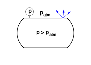
Elastomer O-rings can allow gas to permeate and deform permanently over time (compression set), which decreases leak tightness. Metal seals can achieve very low leak rates but require a higher surface flatness, higher tightening forces, and careful assembly.
Good reporting includes at least: standard or method, tracer gas used, test pressure and temperature, detection limit, measurement duration, calibrations used, measurement uncertainty, and a clear conclusion whether the measured leak rates fall within or outside the agreed leak test requirements.
A pressure test is a trial in which an installation, pipe or component is subjected to overpressure to assess the mechanical strength and practical tightness. Depending on the standard, it is a strength test, a tightness test, or a combination of both.
In a pressure test, you mainly check whether the system can safely handle the test pressure and whether there are no visible leaks at that pressure.
A leak test focuses on accurately quantifying the leak rate, often using sensitive measuring equipment and trace gases, for example in mbar·l/s or Pa·m³/s.
Pressure tests are coarser and intended as a constructive check, leak tests are more detailed and intended to detect micro leaks.
For delivery, inspection moments, and structural assessment, a pressure test is usually sufficient, provided your design and standard allow it. A leak test makes sense when very low leak rates are required, for example with helium leak tightness or fugitive emission requirements. In many cases, a pressure test is performed first and only a leak test is conducted additionally for specific requirements.
A hydrotest is a pressure test with a nearly incompressible medium, usually water. The system is filled, pressurized, and held at test pressure for a certain period of time to assess strength and visible tightness.
Water is practically incompressible, which means the stored energy during a hydrotest is much lower than during a test with gas. In the event of a defect, water will flow out, but no explosive discharge occurs. Therefore, a hydrotest is usually safer, and you can generally also test at higher pressures than with a pneumatic pressure test.
In a hydrotest, testing is done at a clearly defined test pressure, often according to a standard, and in addition to visible leakage, strength and any permanent deformation are also examined. A simple “leak detection test with water” can consist of filling a system to a modest pressure to detect assembly errors. Both are pressure tests, but a standardized hydrotest has stricter requirements for test pressure, test duration, temperature, and evaluation.
No. A hydrotest is primarily a strength and coarse density inspection. You assess visible leakage, such as drops or small streams of water. The sensitivity is limited, no reports are made in mbar·l/s or similar leak rates. For that level of detail, a separate leak test is necessary.
Typically, testing is done at approximately 1.3 to 1.5 times the design pressure or maximum allowable pressure, corrected for material properties at the test temperature. The exact factor depends on the applicable standard, for example ASME or EN, and the type of installation.
The system must be completely filled and vented, valves and safety valves must be positioned according to procedure, and instruments must be suitable for the test pressure. Additionally, attention must be paid to corrosion prevention, drainage, and safe venting afterward.
According to most standards, “no visible leakage” is the criterion. A dripping connection or a sweating weld is then considered a rejection. In practice, a client can still make a distinction between a strength test and a leak test in their specification, but that must be clear in advance.
Yes, that is very important. Residual gas bubbles act like a spring: they store extra energy and can cause a much more violent release when failure occurs than when the test object is completely filled with water. This increases the risk of injury and damage.
In addition, gas bubbles interfere with the measurement: the pressure response becomes less predictable and small leaks or deformations are harder to assess. Therefore, a hydro or burst test should always be preceded by careful filling and venting so that the volume of gas in the system is as small as possible.
A pneumatic pressure test is a pressure test with a compressible gas, for example air or nitrogen. The test pressure is usually closer to the design pressure than with hydrostatic tests, due to the greater safety risks in case of failure.
Pneumatic tests are used when water is undesirable, for example in dry or oxygen-sensitive systems, in instrumentation and in installations where residual water damage or contamination is caused. Sometimes a pneumatic test follows a hydrostatic test, as an additional check for tightness.
Gas is highly compressible and contains much more stored energy at the same pressure than water. In case of failure, that energy can be released abruptly, with risks of fragments and shockwaves. Therefore, test pressure and safety measures in pneumatic tests are stricter, and the test pressure is often lower than in a hydrotest.
Many codes use a test pressure of approximately 1.1 to 1.25 times the design pressure. The exact value depends on the standard and the ratio between allowable stresses at test and operating temperatures. Pneumatic tests are almost never performed up to burst pressure; burst tests are intended for that.
Usually the pressure is maintained for a certain period of time and checked for pressure drop and audible or visible leaks, for example with soapy water on suspicious spots. No quantitative leak value in mbar·l/s is reported, unless it is explicitly set up as a leak test.
A burst test is a destructive pressure test in which a component, such as a pipe, fitting, hose, or pressure vessel, is pressurized until it fails. The aim is to determine the burst pressure and verify that sufficient safety margins relative to the design pressure are present.
Burst tests are mainly used in design and type approval processes, for new products or when changing materials or wall thicknesses. They are usually carried out on representative samples, not on all production pieces.
Preferably with an almost incompressible medium, for example water or oil, to limit risks in case of failure. Fracture tests with gas are possible, but require very strict safety measures and a suitable test bunker with associated measuring equipment.
Important are the crack pressure, the location, and the type of failure, for example, longitudinal seam, weld, connection, or base material. Furthermore, it is examined whether there is leakage before failure or brittle fracture and whether the behavior of the materials corresponds with the design and the standard.
In many standards and product specifications, the burst pressure must be a multiple of the design pressure, for example 3 or 4 times the maximum operating pressure. The exact factor depends on the product and standard and is demonstrated in the type approval.
Yes, a hydrotest is well suited to detect visible leaks, assembly errors, and mechanical weak points.
For micro leaks at a very low level, a special leak test is required, but for most process installations, a correct hydrotest is the standard.
Standard is (demi)water, due to safety and availability. Gas is chosen if water is not acceptable for the system. If gas is needed, a careful risk analysis must be made in advance and the test pressure is usually lower than for a hydrotest.
Yes. Often a hydrotest is first performed for strength and coarse tightness, followed by a low-pressure pneumatic test for practical tightness, or a separate leak test if the specification requires it. The setup and sequence are documented in a test plan.
A pressure test after production or repair is intended to approve the component or system for use. Periodic pressure tests are used to demonstrate over time that the installation is still sufficiently strong and leak-tight. The test pressures and acceptance criteria can differ for these two situations and must be recorded in the maintenance plan.
If technically possible, we first vacuum a test object to a low absolute pressure. This way, we remove most of the air and gases from the system before filling it with water.
The advantage is twofold: you are almost certain that the object is gas-free (much safer in case of failure), and the position of the object during filling and venting becomes less critical because there are hardly any gas bubbles left that can accumulate. This makes the test more predictable, safer, and better reproducible.
At ITIS, it’s simply a given that we offer our customers the best service possible. We understand their needs and desires and are always focused on providing the highest quality service and solutions.